


Table of Contents
Warnings & Important Information _________________________________________________________ 3-4
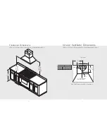
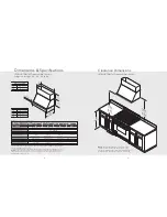
DCH 12”H. Classic Chimney Wall Hoods w/Standard Ventilator
Dimensions & Specifications ______________________________________________________ 5
Clearance Dimensions ____________________________________________________________ 6
Interior Ventilator Dimensions _____________________________________________________ 7
DCWH/DCWN/DCWL Classic Chimney Wall Hoods—
Ledgeless & Ledge 30”, 33”, 36”, 39”, 42”, 45”, 48”, & 51”
Dimensions & Specifications _______________________________________________________ 8
Clearance Dimensions ____________________________________________________________ 9
Interior Ventilator Dimensions ____________________________________________________ 10
Exterior Ventilator Dimensions ___________________________________________________ 11
DCIH Classic Chimney Island Hoods 36”, 42”, & 54”
Dimensions & Specifications ______________________________________________________ 12
Clearance Dimensions ___________________________________________________________ 13
Interior Ventilator Dimensions_____________________________________________________ 14
Exterior Ventilator Dimensions ___________________________________________________ 15
DTWS Slim Traditional Wall Hoods 30”, 36”, 42”, & 48”
Dimensions & Specifications _____________________________________________________ 16
Clearance Dimensions ___________________________________________________________ 17
Interior Ventilator Dimensions_____________________________________________________ 18
Exterior Ventilator Dimensions ___________________________________________________19
DTWL/DTWN Tall Traditional Wall Hoods—Ledgeless & Ledge 30”, 36”, 42”, & 48”
Dimensions & Specifications _____________________________________________________ 20
Clearance Dimensions ___________________________________________________________ 21
Interior Ventilator Dimensions ___________________________________________________ 22
Exterior Ventilator Dimensions ___________________________________________________ 23
DSWB Box Wall Hoods 30”, 36”, 42”, & 48”
Dimensions ___________________________________________________________________ 24
Clearance Dimensions ____________________________________________________________ 25
Interior Ventilator Dimensions _____________________________________________________ 26
Exterior Ventilator Dimensions ___________________________________________________ 27
Planning Information________________________________________________________________ 28
Installation Procedure
Installation (DCH 12”H. Classic Chimney Wall Hoods w/Standard Ventilator) ___________ 29
Duct Cover Option (DCH 12”H. Classic Chimney Wall Hoods w/Standard Ventilator)____ 31
Installation (DCH 12”H. Classic Chimney Wall Hoods w/Recirculating Kit) ______________ 32
Installation (DCWH/DCWN/DCWL Classic Chimney &
DTWL/DTWN Tall Traditional Wall Hoods) ________________________________________ 34
Duct Cover Option (DCWH/DCWN/DCWL Classic Chimney Wall Hoods) ______________ 35
Duct Cover Option (DTWL/DTWN Tall Traditional Wall Hoods) _______________________ 36
Installation (DTWS Slim Traditional & DSWB Box Wall Hoods) ________________________ 36
Duct Cover Option (DTWS Slim Traditional Wall Hoods) _____________________________ 38
Duct Cover Required (DSWB Box Wall Hoods) _____________________________________ 39
Installation (DCIH Classic Chimney Island Hoods) ___________________________________ 40
Wiring Diagram _____________________________________________________________________42
Service & Registration_______________________________________________________________ 43
3
IMPORTANT–
Please Read and Follow!
NOTE:
If installing hood with warming shelf panel,
install warming shelf panel first.
IMPORTANT – PLEASE READ AND FOLLOW
• Before beginning, please read these instructions
completely and carefully.
• Do not remove permanently affixed labels, warnings, or
plates from the product. This may void the warranty.
• Please observe all local and national codes and
ordinances. If no local codes are applicable, wire in
accordance with the National Electrical Code,
ANSI/NFPA 70-latest edition.
• Outdoor approved models should be installed in a
covered non-enclosed area and should be protected
from the elements as much as possible.
• The installer should leave these instructions with the
consumer who should retain for local inspector’s use and
for future reference.
• Check with a qualified and trained installer or local codes
for makeup air requirement, if any.
This hood is for residential installation only and is not
designed for installation over a commercial product. Make
sure power is off at the main circuit breaker or fuse box
before making connections. To avoid risk of fire, electric
shock, or injury to persons, turn off the electricity to the
hood from the power supply before servicing or cleaning.
Viking hoods are equipped with the variable speed
controls for blowers. These units will not function with a
single speed ventilator. All Viking ventilator kits are
designed specifically for use with Viking hoods. Use of any
non-Viking ventilator kit will void the hood warranty.
READ AND SAVE THESE INSTRUCTIONS
W A R N I N G
TO REDUCE THE RISK OF A RANGETOP
GREASE FIRE
1. Never leave surface units unattended at high
setting. Boilovers cause smoking and greasy
spillovers that may ignite. Heat oils slowly on
low or medium settings.
2. Always turn hood ON when cooking at high
heat or when cooking flaming foods. (i.e. crepes
suzette, cherries jubilee, peppercorn beef
flambé).
3. Clean ventilating fans frequently. Grease should
not be allowed to accumulate on fan or filter.
4. Use proper pan size. Always use cookware
appropriate for the size of the surface element.
TO REDUCE THE RISK OF FIRE, ELECTRICAL
SHOCK, OR INJURY TO PERSONS, OBSERVE
THE FOLLOWING
1. Installation work and electrical wiring must be
done by qualified person(s) in accordance with
all applicable codes and standards, including
fire-rated construction.
2. Sufficient air is needed for proper combustion
and exhausting of gases through the flute
(chimney) of fuel burning equipment to prevent
back drafting. Follow the heating equipment
manufacturer’s guideline and safety standards
such as those published by the National Fire
Protection Association (NFPA), and the
American Society for Heating, Refrigeration and
Air Conditioning Engineers (ASHRAE), and the
local code authorities.
3. When cutting or drilling into wall or ceiling, do
not damage electrical wiring or other hidden
utilities.
4. Ducted fans must always be vented to the
outdoors.
5.
WARNING!:
To reduce risk of fire, use only
metal ductwork.
6.
CAUTION!:
To reduce risk of fire and to
properly exhaust air, be sure to duct air outside.
Do not vent exhaust air into spaces within walls
or ceilings, or into attics, crawl spaces, or
garages.
7.
CAUTION!:
To Reduce the Risk of Fire and
Electric Shock, Install this rangehood only with
remote blower models manufactured by Viking,
model numbers – DEV900/DEV1200,
VEV900/VEV1200, OR DEV1500, VEV1500 or
integral blowers manufactured by Viking, model
numbers – DIV300, DIV440, DIV600, DIV800,
DIV1200, VIV300, VIV600, or VIV1200. NOTE –
Please refer inside for specific canopy/blower
combinations.
W A R N I N G
W A R N I N G
TO REDUCE THE RISK OF FIRE, ELECTRIC
SHOCK, OR INJURY TO PERSONS, OBSERVE THE
FOLLOWING
• Use this unit only in the manner intended by the
manufacturer. If you have any questions, contact
the manufacturer.
• Before servicing or cleaning unit, switch power off
at service panel and lock service panel to prevent
power from being switched on accidentally. When
the service disconnecting means cannot be locked,
securely fasten a prominent warning device, such
as a tag, to the service panel.


