manualshive.com logo in svg
background image

8

GRAVITY DRAIN

DRAIN PUMP
Model  Number - VUIM-DP

((sso

olld

d  sse

ep

paarraatte

ellyy))

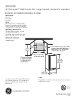
GRAVITY DRAIN  LOCATION

5/8” (.63 cm) ID
drain tubing and
hose clamp

1 1/2” (3.8 cm)
drain pipe

Drain trap

(“p” trap)

Drain from
ice machine

Access
panel

Access
panel

ice machine power cord

Tubing clamps

Vent tube

Discharge tube
goes through this opening in the
access panel  (See installation
instructions supplied with drain pump.)

Drain pump power cord

Vent tube -
goes through
this opening
in the access
panel

T

To

op

p  o

off

U

Un

niitt

F

Frro

on

ntt  o

off

U

Un

niitt

22” (55.9 cm)

24 5/8” (62.6 cm)

2 3/8” (6.0 cm)

4 1/16”

(10.3 cm)

14 3/4”

(37.5 cm)

6 3/4”

(17.1 cm)

DRAIN PLUMBING

Your ice machine uses a gravity drain that requires 5/8” (.63 cm) ID tubing from the back of the
ice maker to a plumbed connection to a sanitary sewer (see Gravity Drain drawing below).
Remove the access panel, with a 5/16” (0.8 cm) wrench to plumb in drain connection.  Gravity
drain location for built-in units can be within the area shown in illustration below.  

An optional

drain pump can be purchased for your ice machine if a gravity drain is not accessible.
Observe and follow all local codes when installing an ice machine.

F

Faaiillu

urre

e  tto

o  u

usse

e  aad

de

eq

qu

uaatte

e

d

drraaiin

naag

ge

e  ssyysstte

em

m  w

wiillll  rre

essu

ulltt

iin

n  ssu

urrrro

ou

un

nd

diin

ng

g  w

waatte

err

d

daam

maag

ge

e  aan

nd

d//o

orr  p

po

oo

orr  iicce

e

p

prro

od

du

uccttiio

on

n..

WARNING

Содержание VUIM150DLSS

Страница 1: ...y yo ou ur r i ic ce e m ma ac ch hi in ne e i is s located so the front is not blocked to restrict incoming or discharge air flow properly leveled located in a well ventilated area properly connected...

Страница 2: ...hree sides but the front M MU US ST T B BE E unobstructed for air circulation and proper operation Installation should be such that the cabinet can be moved for servicing if necessary 2 Unit should be...

Страница 3: ...E El le ec ct tr ri ic c D Da at ta a 115 VAC 60 Hz Maximum amps 3 0 Approximate Shipping Weight 110 lbs 49 5 kg Front View Side View 34 1 4 87 0 cm 22 55 9 cm 27 1 8 68 9 cm 24 5 8 62 6 cm 37 9 16 95...

Страница 4: ...l le ec ct tr ri ic c D Da at ta a 115 VAC 60 Hz Maximum amps 3 0 Approximate Shipping Weight 110 lbs 49 5 kg Front View Side View 34 1 4 87 1 cm 22 55 9 cm 25 5 8 65 1 cm 24 5 8 62 6 cm 37 9 16 95 4...

Страница 5: ...st you in tilting the unit to prevent it from falling on you while installing the leg levelers 2 Screw front two leg levelers into the screw impressions Leg levelers should be screwed in until snug 3...

Страница 6: ...R S SU UP PP PL LY Y C CO OR RD D G GR RO OU UN ND D P PL LU UG G D DO O N NO OT T U US SE E A AN N E EX XT TE EN NS SI IO ON N C CO OR RD D R Re ec co om mm me en nd de ed d G Gr ro ou un nd di in n...

Страница 7: ...m drain tube connection barbed connection Make certain all hose clamps are secure A A w wa at te er r f fi il lt te er r i is s r re ec co om mm me en nd de ed d f fo or r t th hi is s u un ni it t A...

Страница 8: ...1 cm DRAIN PLUMBING Your ice machine uses a gravity drain that requires 5 8 63 cm ID tubing from the back of the ice maker to a plumbed connection to a sanitary sewer see Gravity Drain drawing below...

Страница 9: ...ires During the harvest cycle the drain valve will remain open for 45 seconds to drain the reservoir of remaining deposits After that the water valve will open for 2 minutes providing 2 quarts of wate...

Страница 10: ...al ll lo ow w i ic ce e b bi in n t to o f fi il ll l t to o s sh hu ut t o of ff f t th he er rm mi is st to or r APPROXIMATE TIME TO FILL BIN HOURS WATER TEMPERATURE 0 F Outdoor Use 1 For best perf...

Страница 11: ...bottom of the reservoir to drain any remaining water and then reinstall 3 Remove the escutcheon panel 4 Add cleaning solution to the reservoir NOTE Three quarts of water will automatically be added to...

Страница 12: ...en the drain valve to drain the reservoir and the ice machine drain system 5 Unplug the unit from the electrical outlet 6 Remove the back panel from the rear of the unit 7 Disconnect the water valve s...

Страница 13: ...ure they are not restricted or plugged Distributor tube is restricted See Cleaning the Ice Machine System section for cleaning the unit for proper operation Build up of deposits on evaporator See Clea...

Страница 14: ...o an area where temperature is below 90o F Ice cubes are too big Ice slab not releasing See Cleaning the Ice Machine System greater than 3 4 thick section for cleaning the unit for proper operation Co...

Страница 15: ...s to run Ice bin is not full The unit will automatically shut down when and produce ice ice reaches the sensing tube Ice bin is full The unit will automatically shut down when ice reaches the sensing...

Страница 16: ...fied plumber Foreign material in ice bin drain Foreign material is restricting or blocking the ice bin drain located at the right rear corner of the ice bin The drain will need to be cleared Water kee...

Страница 17: ...be obtained from the dealer or distributor in your area 2 Have the following information readily available Model number Serial number Date of purchase Name of dealer from whom purchased If you are una...

Страница 18: ...orporation service agency or representative Warranty shall not apply to damage resulting from indoor units being used in outdoor situations This warranty does not apply to commercial usage Warrantor i...

Страница 19: ...in outdoor situations This warranty does not apply to commercial usage Warrantor is not responsible for consequential or incidental damage whether arising out of breach of warranty breach of contract...

Страница 20: ...Front Street Greenwood Mississippi USA 38930 662 455 1200 Specifications subject to change without notice For more product information call 1 888 VIKING1 845 4641 or visit our web site at http www vik...

Отзывы: