manualshive.com logo in svg
background image

1

S

1

IMPORTANTE - Lea y siga las instrucciones

• antes de comenzar, lea estas instrucciones completa y detalladamente.
• asegúrese de DESCONECTaR el horno microondas del tomacorriente eléctrico antes de instalar el juego de moldura para

empotrado. Retire el plato giratorio de la cavidad del horno.

• El juego incluye partes de metal por lo que debe manipularlo e instalarlo con precaución para evitar el riesgo de lesiones.
• No retire las etiquetas, advertencias o placas permanentes del producto. Esto puede anular la garantía.
• Cumpla todos los códigos y normas locales y nacionales.

• El instalador debe devolver estas instrucciones al cliente quien debe conservarlas para uso del inspector local y para

referencias futuras.

• Este juego de molduras para empotrado está diseñado para usarlo SÓLO CON HORNOS mICROONDaS DE CONvECCIÓN

y CONvENCIONaLES QUE ESPECIfIQUEN EL JUEGO DE mOLDURaS PaRa EmPOTRaDO vmTk272, vmTk302, vmTk362,

vmTk277, vmTk307 o vmTk367 en la etiqueta de potencia en la placa de la parte inferior de la cavidad del horno.

• EL HORNO PUEDE SER CONSTRUIDO EN UN GaBINETE O EN La PaRED POR Sí mISmO O POR ENCIma DE CUaLQUIER 

HORNO DE PaRED ELÉCTRICO O EL CaJÓN CaLENTaDOR.

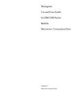
Minimum Cutout Opening Width 24-3/8" (619.13 mm)

Maximum Cutout Opening Width 24-11/16" (627.06 mm)

M

inimum C

ut

out Op

ening H

eigh

t 16

-3/4" (425.5 mm)

M

aximum C

ut

out Op

ening H

eigh

t 17" (431.8 mm)

M

aximum  H

eigh

t  distanc

e b

et

w

een holes 14-1/4" (361.825 mm)

Distance between centerline to holes 12-13/16" (324.65 mm)

Distance between holes 

A

 25-9/16" (649.3 mm)

Distance between centerline to holes 14-5/16" (362.75 mm)

Distance between holes 

B

 28-9/16" (725.5 mm)

15-13/32" (391.45 mm)

Center Line

BUILT-IN TRIM KIT TEMPLATE

FOR CUSTOM SERIES MICROWAVE OVEN

1.  Align the mounting template center line with the center of the cutout 

and the floor line with the floor of the cutout.  Tape it into place.

2. For 

VMTK272, predrill 4 holes marked 

A

 with a 1/16" drill bit.

 For 

VMTK302, predrill 4 holes marked 

B

 with a 1/16" drill bit.

3.  Remove template from the cabinet.

TINSKB182MRR0

Floor Line of Cutout Opening

USE THIS SIDE OF TEMPLATE FOR MODELS

VMTK272 and VMTK302 ONLY.

1-5/32"

(29.6 mm)

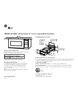
Partes incluidas en los juegos VMTK

marco frontal


CANT. 1

nuevo marco de 

CANT. 1

Conjunto del marco


CANT.

 1

Conjunto de ducto inferior


CANT.

 1

Tornillo A (1/2" de largo) 

CANT.

 10 *

Tornillo B (1-3/4" de 

largo) 

CANT.

 4

Plantilla para montaje en superficie 

de dos caras de 27" y 30"  

o plantilla para montaje en

superficie de una cara de 36"

CANT. 1

*

Cojín 

CANT.

 3

Ducto (A)-1


CANT.

 1 *

Ducto (A)-3


CANT.

 1 *

Ducto (B)


CANT.

 1 *

Ducto (C)


CANT.

 1 *

Ducto (A)-2


CANT.

 1 *

Tornillo C (3/4" de largo) 

CANT.

 2

*

SÓLO

 VMTK277, VMTK307 y VMTK367.

Содержание VMTK272

Страница 1: ...Installation Guide Microwave Built In Trim Kit VMTK272 VMTK302 VMTK362 VMTK277 VMTK307 VMTK367 ...

Страница 2: ... microwave oven from the electrical outlet before installing the built in trim kit Remove the turntable from the oven cavity Because the kit includes metal parts caution should be used in handling and installation to avoid the possibility of injury Do not remove permanently affixed labels warnings or plates from the product This may void the warranty Please observe all local and national codes and...

Страница 3: ... Maximum Amp Usage 1 55 KW 1 5 KW 13 amps UL 13 CSA N A Approximate Shipping Wt 60 lbs 27 2 kg 19 lbs 8 6 kg 20 lbs 9 1 kg 23 lbs 10 5 kg Description CONVENTIONAL VMOS201 CVMOS201 VMTK272 VMTK302 VMTK362 Overall Width 24 60 9 cm 26 1 2 67 3 cm 29 1 2 74 9 cm 35 1 4 89 5 cm Overall Height from Bottom 13 3 8 33 9 cm 18 1 4 46 3 cm 18 1 4 46 3 cm 18 1 4 46 3 cm Overall Depth from Rear 19 1 4 48 9 cm ...

Страница 4: ...6 62 7 cm C Depth Min 20 1 8 51 1 cm Min 20 1 8 51 1 cm D Min Max 6 11 1 2 15 2 cm 29 2 cm E Min Max 4 5 10 2 cm 12 7 cm ELECTRICAL OUTLET LOCATION Outlet should NOT be in the shaded area as indicated on figure 1 At the rear of the opening provide a 3 pronged polarized electrical outlet 115 120 volt AC 15 amp or larger 2 DUCT C DUCT B SCREW A EXHAUST DUCT ASSEMBLY Insert the edge of DUCT B into th...

Страница 5: ... bit For VMTK307 only predrill 4 holes marked B with a 1 16 drill bit For VMTK362 only predrill 4 holes marked C with a 1 16 drill bit For VMTK367 only predrill 4 holes marked C with a 1 16 drill bit Remove template from the cabinet A Exhaust Duct Assembly Surface Installation 6 NOTE Center Bottom Duct Assembly in the opening DETAIL A GAP B BOTTOM DUCT ASSEMBLY SCREW C BOTTOM DUCT ASSEMBLY Place t...

Страница 6: ...essory kit PURCHASED SEPARATELY 2 Stainless Steel Scoops 10 Stainless Machine Screws 1 Flush Mount Template 2 Side Trim See FLUSH MOUNT Template for additional installation instructions Flush Mount INSTALLATION Place the 2 Scoops on the back of the frame as shown and align the screw holes on the scoop with the tapped holes in the frame Secure the scoops to the frame using 6 of the machine screws p...

Страница 7: ...below are not to be installed above gas ovens VMTK272SS VMTK307SS VMTK362SS VMTK277SS VMTK302SS VMTK367SS Flush Mount Installation CONVECTION CONVENTIONAL 27 30 36 27 30 36 A Height 21 5 16 542 cm 21 5 16 542 cm 21 5 16 542 cm 19 7 8 504 cm 19 7 8 504 cm 19 7 8 504 cm B Width 26 15 16 68 3 cm 29 15 16 76 cm 35 5 8 90 4 cm 26 15 16 68 3 cm 29 15 16 76 cm 35 5 8 90 4 cm C Depth 22 1 16 56 1 cm 22 1 ...

Страница 8: ...Guide d installation Kit de garniture à encastrer pour four à micro ondes VMTK272 VMTK302 VMTK362 VMTK277 VMTK307 VMTK367 F ...

Страница 9: ... Minimum Cutout Opening Width 24 3 8 619 13 mm Maximum Cutout Opening Width 24 11 16 627 06 mm Minimum Cutout Opening Height 16 3 4 425 5 mm Maximum Cutout Opening Height 17 431 8 mm Maximum Height distance between holes 14 1 4 361 825 mm Distance between centerline to holes 12 13 16 324 65 mm Distance between holes A 25 9 16 649 3 mm Distance between centerline to holes 14 5 16 362 75 mm Distance...

Страница 10: ... O Ampèrage max 1 55 KW 1 5 KW 13 amps UL 13 CSA S O Poids approx à l expédition 60 lbs 27 2 kg 19 lbs 8 6 kg 20 lbs 9 1 kg 23 lbs 10 5 kg Descriptión TRADITIONNEL VMOS201 CVMOS201 VMTK272 VMTK302 VMTK362 Largeur hors tout 24 po 60 9 cm 26 1 2 po 67 3 cm 29 1 2 po 74 9 cm 35 1 4 po 89 5 cm Hauteur hors tout depuis le bas 13 3 8 po 33 9 cm 18 1 4 po 46 3 cm 18 1 4 po 46 3 cm 18 1 4 po 46 3 cm Profo...

Страница 11: ...1 cm D Min Max 6 po 11 1 2 po 15 2 cm 29 2 cm E Min Max 4 5 10 2 cm 12 7 cm Emplacement De La Prise Électrique La prise NE doit PAS se trouver dans l aire ombrée comme indiqué à schéma 1 À l arrière de l ouverture installer une prise électrique polarisée pour fiche à trois broches 115 120 volt CA 15 A ou plus 2 CONDUIT C CONDUIT B VIS A schéma schéma ENSEMBLE DU CONDUIT D ÉVACUATION Insérer le bor...

Страница 12: ... 6 mm Pour VMTK302 uniquement percer les 4 trous marqués B avec un foret de 1 16 po 1 6 mm Pour VMTK307 uniquement percer les 4 trous marqués B avec un foret de 1 16 po 1 6 mm Pour VMTK362 uniquement percer les 4 trous marqués C avec un foret de 1 16 po 1 6 mm Pour VMTK367 uniquement percer les 4 trous marqués C avec un foret de 1 16 po 1 6 mm Enlever le gabarit de l armoire 6 REMARQUE ENSEMBLE DU...

Страница 13: ...ce que ses pattes entrent dans les évidements de l ENSEMBLE DU CONDUIT INFÉRIEUR Voir schéma 8 9 VIS B VIS B VIS B VIS B schéma schéma INSTALLATION DU CHÂSSIS Placer le CHÂSSIS ARRIÈRE pour qu il soit aligné avec les trous percés à l aide du gabarit Vérifier qu il est de niveau puis le fixer avec quatre VIS B Voir schéma 9 Fixer la partie inférieure de l ENSEMBLE DU CHÂSSIS avec deux VIS B restant...

Страница 14: ... Placer la décoration AVANT sur le CADRE et aligner les pivots à rotule avec les récepteurs Fixer la DÉCORATION sur le CADRE en poussant fermement le cadre avant sur le cadre arrière en engageant les quatre 4 fixations à pression Voir schéma Découpe pour le micro ondes Découpe du Four Inférieur schéma schéma INSTALLATION AU DESSUS D UN FOUR L espace entre les micro ondes et le four inférieur 5 08 ...

Страница 15: ...Instrucciones de Instalación Juego de Molduras para Empotrado para Horno Microondas VMTK272 VMTK302 VMTK362 VMTK277 VMTK307 VMTK367 S ...

Страница 16: ...4 3 8 619 13 mm Maximum Cutout Opening Width 24 11 16 627 06 mm Minimum Cutout Opening Height 16 3 4 425 5 mm Maximum Cutout Opening Height 17 431 8 mm Maximum Height distance between holes 14 1 4 361 825 mm Distance between centerline to holes 12 13 16 324 65 mm Distance between holes A 25 9 16 649 3 mm Distance between centerline to holes 14 5 16 362 75 mm Distance between holes B 28 9 16 725 5 ...

Страница 17: ...máx en amperios 1 55 KW 1 5 KW 13 amps UL 13 CSA N A Peso aproximado de embarque 60 lbs 27 2 kg 19 lbs 8 6 kg 20 lbs 9 1 kg 23 lbs 10 5 kg Descripción CONVENCIONAL VMOS201 CVMOS201 VMTK272 VMTK302 VMTK362 Ancho total 24 60 9 cm 26 1 2 67 3 cm 29 1 2 74 9 cm 35 1 4 89 5 cm Altura total desde la parte inferior 13 3 8 33 9 cm 18 1 4 46 3 cm 18 1 4 46 3 cm 18 1 4 46 3 cm Profundidad total desde la par...

Страница 18: ... 15 2 cm 29 2 cm E mín máx 4 5 10 2 cm 12 7 cm UBICACIÓN DEL TOMACORRIENTE ELÉCTRICO El tomacorriente NO debe estar en el área sombreada como se indica en la figura 1 En la parte posterior de la abertura debe haber un tomacorriente eléctrico de tres clavijas polarizado de 115 120 volt CA 15 amperios o mayor 2 DUCTO C DUCTO B TORNILLO A figura figura ENSAMBLAJE DEL DUCTO DE ESCAPE Inserte el extrem...

Страница 19: ...como B con una broca de 1 16 Sólo para VMTK307 taladre 4 agujeros marcados como B con una broca de 1 16 Sólo para VMTK362 taladre 4 agujeros marcados como C con una broca de 1 16 Sólo para VMTK367 taladre 4 agujeros marcados como C con una broca de 1 16 Retire la plantilla del gabinete 6 NOTA CENTRE EL CONJUNTO DEL DUCTO INFERIOR EN LA ABERTURA DETALLE A SEPARACIÓN B CONJUNTO DE DUCTO INFERIOR TOR...

Страница 20: ...e bolas 10 Tornillos inoxidables de máquina 1 Plantilla para montaje al ras 2 Molduras laterales Vea PLANTILLA DE MONTAJE AL RAS para instrucciones adicionales de instalación figura Instalación del montaje al ras Coloque las 2 paletas en la parte posterior del marco como se muestra en la imagen y alinee los agujeros de los tornillos de la paleta con los agujeros de colada del marco Asegure las pal...

Страница 21: ...uía de instalación y que se enumeran a continuación NO DEBEN SER INSTALADOS POR ENCIMA DE HORNOS A GAS VMTK272SS VMTK307SS VMTK362SS VMTK277SS VMTK302SS VMTK367SS CONVECCIÓN CONVENCIONAL 27 30 36 27 30 36 A Altura 21 5 16 542 cm 21 5 16 542 cm 21 5 16 542 cm 19 7 8 504 cm 19 7 8 504 cm 19 7 8 504 cm B Peso 26 15 16 68 3 cm 29 15 16 76 cm 35 5 8 90 4 cm 26 15 16 68 3 cm 29 15 16 76 cm 35 5 8 90 4 c...

Страница 22: ......

Страница 23: ......

Страница 24: ...TINSLB035MRR0 Viking Range LLC 111 Front Street Greenwood Mississippi 38930 USA 662 455 1200 For more product information call 1 888 845 4641 ...

Отзывы: