Page
6
of 10
TrueSafeTS12CLR User Manual
V1.1
5.
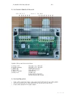
Connector details of the unit
A B C D E F G H I J K L M N
Details of the connectors are as follows:
A: Relay 1 NO
G:Supply (+ve) –DC+12V
B: Relay1 Common
H:Supply (-ve) – DC GND
C:Relay1 NC
I:Gas Valve (V coil +)
D:Relay2 NO
J:Gas Valve (V coil -)
E:Relay 2 Common
K:RS485 (D+)
F:Relay 2 NC
L:RS485 (D-)
M:Valve Status Input (DI)
N:Valve Status Input Ground.
6.
Connecting wires
•
Take out the wires from supply, relay output and RS 485 port through cable glands.
•
Make the connections for relay and RS 485 as mentioned in above table.
•
Insert power adapter to the mains socket.


