VP171
A1T020100001
VLCDS25972-1W
DVI-DVI Cable
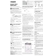
1.
Connect P2 and P4 of Fixture with VGA ports of VP171
/s/b
by two VGA Cables.
2.
Connect P3 of Fixture with DVI port of VP171
/s/b
by DVI-D Cable.
3.
Connect P1 of Fixture with COM1 of PC by RS232 Cable.
4.
Plug Power Adapter to Fixture.
5.
Connect Power Cord to VP171
/s/b
Monitor, and turn on the Power Switch.
6.
Connect PC to the additional monitor.
P3 : to DVI-DVI
Cable
JP1 : to
Power
Adapter
P1 : to
RS232 Cable
P2 & P4 : to VGA Cables
Power Adapter for Fixture
(P/N: 47.56001.501)
VGA Port
Connect to
Power Cord
Turn on the Power Switch
DVI Port
ViewSonic Corporation
48
Confidential
– Do Not Copy
VP171/b/s
Set-Up Procedure
7-2
Содержание VLCDS25972-1W
Страница 13: ...2 2 Exploded Overview ViewSonic Corporation 8 Confidential Do Not Copy VP171 b s ...
Страница 46: ...ViewSonic Corporation 41 Confidential Do Not Copy VP171 b s ...
Страница 47: ...ViewSonic Corporation 42 Confidential Do Not Copy VP171 b s ...
Страница 59: ...5 Tape the carton closed LabelFormat Label ViewSonic Corporation 54 Confidential Do Not Copy VP171 b s ...
Страница 69: ...10 PCB Layout ViewSonic Corporation 64 Confidential Do Not Copy VP171 s b 1 ...
Страница 70: ... ViewSonic Corporation 65 Confidential Do Not Copy VP171 s b 1 ...
Страница 71: ... ViewSonic Corporation 66 Confidential Do Not Copy VP171 s b 1 ...
Страница 72: ... ViewSonic Corporation 67 Confidential Do Not Copy VP171 s b 1 ...