


Vitosol 100-FM/200-FM Installation, Operating and Service
5786 604 - 02
20
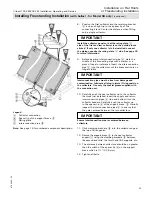
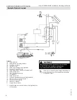
Install the collector panel so that the rating plate
C
side of the first and last collector is on the outside (note
sticker)! If only one collector is to be installed, connect
the piping opposite the rating plate
C
side. See page 30
for more information.
8. Before inserting interconnection pipe
D
mark the
middle of the connecting pipe with a marker or a piece
of tape for reference. Insert the interconnection pipe
D
into the collector until the brass section is no
longer
visible.
Interconnecting pipes must be free from damage and
contamination. Lubricate all plug-in joints (O-ring seals) on
the collectors. Use only the special grease supplied with
the connection set.
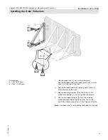
9. Carefully push the next collector up to the collector
that was just installed. Insert the supply and return
interconnection
pipes
D
(top and bottom) into the
collector headers. Carefully push the collector up
to the spacer lip
B
of the support brace
. Visually
inspect the interconnection pipes
D
to ensure that
they are centered between the two collectors.
Ensure interconnection pipe is centered between
collectors.
10. Click clamping brackets
qP
into the collector edge
at the top of all supports.
11. Secure the support brace
to the next collector
support
1
using the clamping brackets
qP
between
the second and third, the fourth and fifth supports, etc.
12. The distance between collectors should be no greater
than the width of the spacer lip
B
on the support
brace which is 1
a
” (32.8 mm).
13. Tighten all bolts.
Installing Freestanding Installation on Substructures
(continued)
Legend
A
Collector
connection
B
Spacer lip of the support brace
C
Rating
plate
D
Interconnection
pipe
qE
Note:
See page 15 or 16 (depending on model) for
numbered component description.
IMPORTANT
IMPORTANT
IMPORTANT
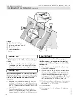
Installation on Flat Roofs
or Freestanding Installation


