


6
Calling up the service menu ............................................................... 48
Exiting the service menu .................................................................... 48
Diagnosis: General sub-menu ............................................................ 48
Diagnosis: Boiler sub-menu ................................................................ 49
Diagnosis: Heating sub-menu ............................................................ 49
Diagnosis: DHW sub-menu ................................................................ 49
Diagnosis: KM BUS sub-menu ........................................................... 49
Calling up operating conditions and sensors ......................................... 50
Checking and acknowledging faults ................................................... 51
Calling up acknowledged fault messages .......................................... 51
Calling up fault codes from the fault memory (fault history) ............... 51
Deleting the fault codes from the fault memory .................................. 52
Triggering the function ........................................................................ 55
Cancelling the function ....................................................................... 55
Carrying out an actuator test ................................................................. 56
Checking sensors .................................................................................. 57
Lambda probe ........................................................................................ 58
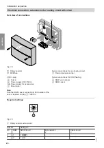
Extension kit components ...................................................................... 59
Specification .......................................................................................... 59
Mixer motor ............................................................................................ 60
Changing the rotational direction (if required) .................................... 60
13. Connection and wiring dia-
PCB KSK 2.01b ..................................................................................... 61
Connections ........................................................................................... 62
230 V connection ................................................................................ 62
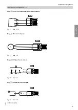
............................................................................................... 64
............................................................................................. 64
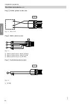
............................................................................................. 66
: Lambda probe .................................................................... 66
: Flow temperature sensor ..................................................... 67
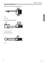
: Return temperature sensor .................................................. 67
........................................................................... 67
: Buffer cylinder sensor .......................................................... 68
: KM BUS .............................................................................. 68
Plug X15: CAN BUS ........................................................................... 69
A: Fan ................................................................................... 69
Index
Index
5684984


