16
Overview of lower connector strip
Pt1000
Pt1000
R
W
B
21
22
23
1
21
22
23
146
21
22
23
15
21
22
23
100A
S3
T2
T1
L1
PE
N
100
50A
M
1~
L
N
+
-
Θ
Θ
A
B
C
D
E
F
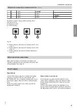
Fig. 6
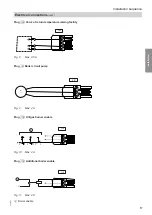
Overview of electrical connections, lower plug-in strip
A
Plug
!
: Outside temperature sensor
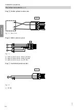
B
Plug
aVH
: N/A
C
Plug
aG
: Flue gas temperature sensor
D
Plug
a¢Ö
A: Hall sensor, flue gas fan
E
Plug
gÖ
A: External fault message
F
Plug
a¢Ö
: Flue gas fan
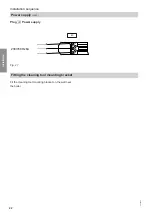
Electrical connection
Plug
aVG
: KM BUS for extension kits
21
22
23
KM-
BUS
145
Fig. 7
For extension kit installation:
Extension kit installation instructions
For mixer module settings:
See page 20.
Installation sequence
Electrical connections
(cont.)
5684984
Installation


