background image

5 of 13

Product

Instructions

PI-PR 566440 0114 (Programmable Heat-Cool Thermostat)

Viega LLC, 301 N. Main, 9th Floor • Wichita, KS 67202 • Ph: 800-976-9819 • Fax: 316-425-7618

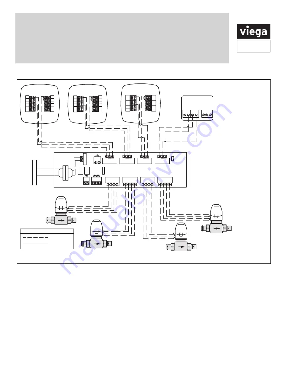
Viega wiring diagrams

ZONE CONTROL (18060, 18062)

WITH OPTIONAL PRIORITY

OFF
ON

ZONE 4 PRIORITY

ZONE 1

ZONE 2

ZONE 3

ZONE 4

ZONE 4 RELAY

N/O

N/C

COM

PUMP

END

SWITCH

ISOLATED

END

SWITCH

ZONE 1

ZONE 2

ZONE 3

ZONE 4

FUSE

(5 AMP MAX)

POWER IN

WC

R

W C

R

W C

R

WC

R

1 2 3 4

120 V AC

Power Supply

L

N

R

C

C C R W

NTC A/B

Thermostat -18050

1 2 3 4

1 2 3 4

C

O

B

W

RH

RC

G

Y

Thermostat -15116

C

O

B

W

RH

RC

G

Y

Thermostat -15117

C

O

B

W/E

RH

G

Y

Thermostat -15118

W2

Y2

RC

Viega

Yellow

Yellow

Red

Red

Viega

Yellow

Yellow

Red

Red

Viega

Yellow

Yellow

Red

Red

Viega

Yellow

Yellow

Red

Red

Line Voltage

Low Voltage

LEGEND: Zone Controls

Part Numbers:

15116, 15117 and 15118

1.  Connect the "RH" terminal 

from the thermostat to "R" 

terminal on the zone control

2.  Connect the "W"  terminal 

from the thermostat to "W" 

terminal on the zone control, 

for part number 15118 

connect "W/E" terminal from 

the thermostat to "W" terminal 

on the zone control

3.  Connect the "C" terminal from 

the thermostat to the "C" 

terminal on the zone control

Connecting Viega thermostats and zone valves to the Viega zone control

Содержание Programmable Heat/Cool Thermostat

Страница 1: ...uct you are replacing contains mercury dispose of it properly Your local waste management authority can give you instructions on recycling and proper disposal A trained experienced technician must install this product Carefully read these instructions You could damage this product or cause a hazardous condition if you fail to follow these instructions W For vertical mount put one screw top and one...

Страница 2: ...with average temperature and good air circulation NOTE Pick an installation location that is easy for the user to access The temperature of the location should be representative of the building Do not install thermostat in locations Close to hot or cold air ducts That are in direct sunlight With an outside wall behind the thermostat In areas that do not require conditioning Where there are dead sp...

Страница 3: ...heating B Heat pump changeover valve energized in heating C Common wire from secondary side of cooling system transformer Wiring tips RH RC terminals For single transformer systems leave the jumper wire in place between RH and RC Remove jumper wire for two transformer systems Heat pump systems If wiring to a heat pump use a small piece of wire not supplied to connect terminals W and Y C terminal T...

Страница 4: ...of 13 Product Instructions PI PR 566440 0114 Programmable Heat Cool Thermostat Viega LLC 301 N Main 9th Floor Wichita KS 67202 Ph 800 976 9819 Fax 316 425 7618 Typical industry wiring diagrams See page 8 ...

Страница 5: ...B W RH RC G Y Thermostat 15116 C O B W RH RC G Y Thermostat 15117 C O B W E RH G Y Thermostat 15118 W2 Y2 RC Viega Yellow Yellow Red Red Viega Yellow Yellow Red Red Viega Yellow Yellow Red Red Viega Yellow Yellow Red Red Line Voltage Low Voltage LEGEND Zone Controls Part Numbers 15116 15117 and 15118 1 Connect the RH terminal from the thermostat to R terminal on the zone control 2 Connect the W te...

Страница 6: ...E CONTROL 18060 18062 WITH OPTIONAL PRIORITY OFF ON ZONE 4 PRIORITY ZONE 1 ZONE 2 ZONE 3 ZONE 4 ZONE 4 RELAY N O N C COM PUMP END SWITCH ISOLATED END SWITCH ZONE 1 ZONE 2 ZONE 3 ZONE 4 FUSE 5 AMP MAX POWER IN WC R WC R WC R WC R 1 2 3 4 120 V AC Power Supply L N Viega Viega Viega Yellow Yellow Red Red Yellow Yellow Red Red Viega Yellow Yellow Red Red R C C C R W NTC A B Thermostat 18050 POWERHEAD ...

Страница 7: ... adjust the room temperature 7 User Buttons Menu Tech Setup Set Time Set Sched Important The low battery indicator is displayed when the AA battery power is low If the user fails to replace the battery within 21 days the screen will only show the low battery indicator but maintain all functionality If the user fails to replace the batteries after an additional 21 days days 22 42 since first low ba...

Страница 8: ...erate the fan when the fan relay is connected to the G terminal Fahrenheit Celsius display Select F or C with the jumper pin on the back of the thermostat For Fahrenheit install the jumper pin on the top two pins For Celsius install the jumper pin on the bottom two pins 12 or 24 hour time 12 or 24 hour military time can be selected with the jumper pin For 12 hour time install the jumper pin on the...

Страница 9: ...n is recommended even if thermostat is hardwired C terminal connected When thermostat is hardwired and batteries are installed the thermostat will activate a compressor delay of 5 minutes when the thermostat detects a power outage from the hardwired power supply batteries included Important High quality alkaline batteries are recommended Rechargeable batteries or low quality batteries do not guara...

Страница 10: ...and you would like it to read 72 then select 2 This feature allows the installer to select the minimum run time for the compressor For example A setting of 4 will force the compressor to run for at least 4 minutes every time the compressor turns on regardless of the room temperature The compressor short cycle delay protects the compressor from short cycling This feature will not allow the compress...

Страница 11: ...Default Program Day of the Week Events Time Setpoint Temperature Heat Setpoint Temperature Cool Weekday Wake 6 a m 70 F 21 C 75 F 24 C Leave 8 a m 62 F 17 C 83 F 28 C Return 6 p m 70 F 21 C 75 F 24 C Sleep 10 p m 62 F 17 C 78 F 26 C Saturday Wake 8 a m 70 F 21 C 75 F 24 C Leave 10 a m 62 F 17 C 83 F 28 C Return 6 p m 70 F 21 C 75 F 24 C Sleep 11 p m 62 F 17 C 78 F 26 C Sunday Wake 8 a m 70 F 21 C ...

Страница 12: ... Press SET SCHED NOTE Monday Friday is displayed and the WAKE icon is shown You are now programming the wake time period for the weekday setting 4 Time is flashing Use the or key to make your time selection for the weekday WAKE time period 5 Press NEXT STEP 6 The setpoint temperature is flashing Use the or key to make your setpoint selection for the weekday wake period 7 Press NEXT STEP 8 Repeat s...

Страница 13: ...32 C Loading Rate 1 amp per terminal 1 5 amp maximum all terminals combined Display accuracy 1 F Swing cycle rate or differential Heating is adjustable from 0 2 F to 2 0 F Cooling is adjustable from 0 2 F to 2 0 F Power source 18 to 30 VAC NEC Class II 50 60 Hz for hardwire common wire Battery power from 2 AA alkaline batteries Operating ambient 32 F to 105 F 0 C to 41 C Operating humidity 90 non ...

Отзывы: