background image

Operation

Vidikron Vision Model 65/Model 75 Installation/Operation Manual

49 

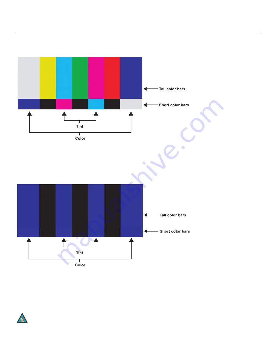
Color: 

On your external test pattern source, select a color bar pattern like the one shown in 

Figure 4-4. 

Figure 4-4. Typical Color Bar Pattern for Adjusting Color Saturation and Tint

Select Color from the Picture Adjust menu and press 

ENTER

. While looking at the color bar 

pattern through a blue filter, adjust the color saturation level until the outermost (gray and 
blue) color bars appear to be a single shade of blue: 

Tint: 

Tint or “hue” is essentially the ratio of red to green in the color portion of the image. 

When tint is decreased, the image appears redder; when it is increased the image appears 
greener. To set the tint, select Tint from the Picture Adjust menu and press 

ENTER

. While 

looking at the color bar pattern through a blue filter, adjust the tint level until the cyan and 
magenta color bars (on either side of the green bar) appear to be a single shade of blue. 

Like the Brightness and Contrast controls, the color and tint controls are 
interactive. A change to one may require a subtle change to the other in 
order to achieve the optimum setting. 

gray

yellow

cyan

gr

een

magenta

re

d

blue

gray

yellow

cyan

gr

een

magenta

re

d

blue

Note

Содержание Vision 65

Страница 1: ...heater Projectors Vision 65 Vision 65 CineWide Vision 65 CineWide with AutoScope Vision 75 Vision 75 CineWide Vision 75 CineWide with AutoScope 65 75 VERSION 1 1 I N S T A L L A T I O N O P E R A T I...

Страница 2: ......

Страница 3: ...ue to defects in materials or workmanship for a period of six 6 months or 1000 hours whichever comes first from the effective date of delivery to the initial end user Such replacement parts are then s...

Страница 4: ...ed Warranty begins on the date of delivery to the end user For your convenience keep the original bill of sale as evidence of the purchase date Repairs made under the terms of this Limited Warranty co...

Страница 5: ...l information about this Limited Warranty please call or write VIDIKRON c o RUNCO INTERNATIONAL LLC 1195 NW Compton Drive Beaverton OR 97006 1992 Ph 503 748 5799 Fax 503 748 8161 Toll Free 888 4VIDIKR...

Страница 6: ...apparatus When a cart is used use caution when moving the cart apparatus to avoid injury from tip over 13 Unplug this apparatus during lightning storms or when unused for long periods of time 14 Refe...

Страница 7: ...measurement techniques Section 5 Surge immunity test EN 61000 4 6 Electromagnetic compatibility EMC Part 4 Testing and measurement techniques Section 6 Conducted disturbances induced by radio frequen...

Страница 8: ...Product contains small amounts of tin lead and or mercury Disposal of these materials may be regulated due to environmental considerations Lamp s inside this product contain mercury This product may...

Страница 9: ...WV O O O O O O 3ODVWLF 3DUWV X O O O O O DPS RRU 6ZLWFK O O O O O O 7KHUPDO 6ZLWFK O O O O O O 3 X O O O O O LUHV O O O O O O 3RZHU FRUG O O O O O O VRFNHW O O O O O O 5HPRWH RQWURO X O O O O O O SJ T...

Страница 10: ...WV O O O O O O 3ODVWLF 3DUWV X O O O O O DPS RRU 6ZLWFK O O O O O O 7KHUPDO 6ZLWFK O O O O O O 3 X O O O O O LUHV O O O O O O 3RZHU FRUG O O O O O O VRFNHW O O O O O O 5HPRWH RQWURO X O O O O O O SJ T...

Страница 11: ...trols and Functions 5 Vision 65 75 at a Glance 5 Vision 65 75 Rear Panel 8 Vision 65 75 Remote Control 9 3 Installation 13 Remote Control 13 Notes on Batteries 13 Notes on Remote Control Operation 13...

Страница 12: ...mary Lens Adjustments 33 Focus and Zoom 33 Vertical Lens Shift 33 Changing the OSD Language 33 Adjusting the Picture Orientation 33 Installing and Adjusting the CineWide Anamorphic Lens 34 Cylindrical...

Страница 13: ...5 Model 75 Installation Operation Manual xiii 6 Serial Communications 67 RS 232 Connection and Port Configuration 67 Serial Command Syntax 67 7 Specifications 71 Vision 65 75 Specifications 71 Vision...

Страница 14: ...Table of Contents xiv Vidikron Vision Model 65 Model 75 Installation Operation Manual Notes...

Страница 15: ...Kinley Cylindrical Lens Base Plate and Ceiling Mounting Plate Exploded View 24 3 10 HDMI DVI Source Connections 27 3 11 RGB Connections 28 3 12 Progressive Component Video Connections 28 3 13 Composit...

Страница 16: ...of Figures xvi Vidikron Vision Model 65 Model 75 Installation Operation Manual 4 8 Gain and Offset 59 4 9 CIE 1931 Chromaticity Diagram 61 7 1 Vision 65 75 Dimensions with Optional Fixed Anamorphic Le...

Страница 17: ...line at www Vidikron com If You Have Comments About This Manual Vidikron welcomes your comments about this manual Send them to info Vidikron com Textual and Graphic Conventions Text Conventions The f...

Страница 18: ...e supplemental information CAUTIONS alert users that a given action or omitted action can degrade performance or cause a malfunction WARNINGS appear when a given action or omitted action can result in...

Страница 19: ...t balance and lamp life preservation It also has a newly refined cooling system which increases efficiency and reduces noise levels The Vision 65 75 has been engineered to comply with Imaging Science...

Страница 20: ...e screen at the same time Two 2 HDMI Inputs with High bandwidth Digital Content Protection HDCP HDTV Compatible Parts List Your Vision 65 75 is shipped with the following items If any items are missin...

Страница 21: ...ion 65 75 components Figure 2 1 Vision 65 75 Front Side Top View 1 EXHAUST VENT 2 ZOOM TAB Use this to change the projected image size 3 TOP IR SENSOR 4 LAMP LED Indicates lamp status as follows Off d...

Страница 22: ...turned off to indicate that the lamp is cooling down Red when an internal failure requiring service has occurred 6 TEMP LED Indicates fan status and internal temperature as follows Off during normal o...

Страница 23: ...DOOR Open to access connectors 2 DOOR RELEASE BUTTON 3 CABLE OPENING Pass cables through this opening 4 LAMP MODULE COVER Remove this cover to access the lamp compartment 5 FRONT REAR ADJUSTERS Use t...

Страница 24: ...80p Component YPrPb input for connecting a DVD HD DVD BD player HD set top box or other SD HD source 4 COMPOSITE VIDEO INPUT Standard composite video input for connecting a VCR laser disc player or ot...

Страница 25: ...ither RGB or component YPbPr SD or HD video signals The Vision 65 75 automatically detects the signal format 2 3 Vision 65 75 Remote Control Figure 2 4 shows the Vision 65 75 remote control and the pa...

Страница 26: ...e RGB Press to select the Component 2 RGB input HDMI HDMI 2 Press to select an HDMI input 4 INFO Displays active source signal resolution aspect ratio and other projector status information Cursor Key...

Страница 27: ...t from the Custom 1 or Custom 2 memory preset 7 Aspect Ratio Selection Buttons Use these buttons to select an aspect ratio directly as follows 16 9 For viewing 16 9 DVDs or HDTV programs in their nati...

Страница 28: ...ion Operation Manual 9 Picture In Picture PIP Controls ACT Press to switch to the active window in PIP mode PIP Press to activate PIP mode PIP Press to enlarge the PIP window PIP Press to shrink the s...

Страница 29: ...ote control for a long time remove the batteries to avoid damage from battery leakage Notes on Remote Control Operation Make sure that there is nothing obstructing the infrared beam between the remote...

Страница 30: ...r 25 4 Connect signal sources to the Vision 65 75 27 5 Connect external controller to RS 232 port optional 30 6 Connect 12 volt trigger output to AutoScope lens motor or other equipment optional 31 7...

Страница 31: ...vibrant Table 3 2 Projector Installation Options Advantages Considerations Front Screen Floor Mount Installation Easy to set up Can be moved or changed quickly Easy to access Shares floor space with a...

Страница 32: ...fill the screen Figure 3 1 Estimating Throw Distance Table 3 3 gives the throw ratios for the Vision 65 75 Vision 65 75 CineWide and Vision 65 75 CineWide with AutoScope Table 3 3 Throw Ratios for th...

Страница 33: ...ee Figure 3 2 Figure 3 2 Projector Placement Vision 65 CineWide with AutoScope or Vision 75 CineWide with AutoScope McKinley Lens 1 88 2 19 136 49 158 99 1 41 1 64 135 36 157 44 Table 3 3 Throw Ratios...

Страница 34: ...56 inch 16 9 screen you can shift the image up to 19 60 inches 0 50 meters above or 28 00 inches 0 71 meters below the screen center 1 With no vertical lens shift the lens center and screen center are...

Страница 35: ...ide projectors speakers power amplifiers and elevators 3 4 Installing the Optional CineWide Lens Mount If you are installing a standard non CineWide Vision 65 75 skip this step and proceed with Mounti...

Страница 36: ...r Front Height Adjusters Place the projector upside down on a blanket or other soft surface Then remove the two height adjusters at the front of the projector by turning them counterclockwise until th...

Страница 37: ...ttom of the projector up and around the AutoScope lens motor housing For floor installations where the projector is upright the adapters allow the projector to lie flat on the mounting surface Using t...

Страница 38: ...side of the projector 3 Secure the motor to the projector with the four 4 supplied 10 32 x 1 2 Pan Head Phillips screws item 1 and nylon spacers item 7 4 Secure the AutoScope Ceiling Mount Adapters Pr...

Страница 39: ...rojector ceiling mount kit with those on the bottom of the projector 4 Secure the CineWide base plate and ceiling mounting plate if needed to the projector with the four M6x12mm screws and washers pro...

Страница 40: ...II McKinley Cylindrical Lens Base Plate and Ceiling Mounting Plate Exploded View 1 Place the projector upside down on a blanket or other soft surface 2 Install a nylon spacer item 3 at each mounting h...

Страница 41: ...and for those that want the projector out of sight or have a limited space for projector and audience you can invert the Vision 65 75 and suspend it from the ceiling using a specially designed ceilin...

Страница 42: ...light angle In a ceiling installation you do this by adjusting the ceiling mount For a floor installation turn the four adjustable feet on the bottom of the projector to adjust the projector height an...

Страница 43: ...utton so it pops out Turn the knob clockwise or counter clockwise and pull gently on it to open the door Connecting Source Components to the Vision 65 75 Connect your video sources to the Vision 65 75...

Страница 44: ...ur RGB source has a 15 pin VGA type connector Figure 3 11 RGB Connections Progressive Component Video Connections Connect your progressive component source DVD player or HD set top box to the COMP 2 R...

Страница 45: ...S Video Component Video Connections Use the included cables to connect your composite S Video and component video sources to the Vision 65 75 as shown in Figure 3 13 Figure 3 13 Composite S Video and...

Страница 46: ...on 65 75 see Figure 3 14 For more information about using this connection refer to Serial Communications on page 67 Figure 3 14 RS 232 Control System Connection S VID S VID 1 2 3 4 5 7 8 9 6 D Sub 9 p...

Страница 47: ...15 Figure 3 15 Connecting the 12 Volt Trigger Output to the AutoScope Lens Motor If your home theater contains a retractable screen screen mask or other 12 volt trigger activated equipment connect it...

Страница 48: ...n AutoScope equipped projector turn on the main power switch at the rear of the AutoScope lens motor The lens motor power switch is located next to the AC input see above 3 Turn on the main power swit...

Страница 49: ...enus in French Spanish Italian or German To change the OSD language 1 Press MENU 2 Select Installation from the Main Menu and press ENTER 3 Select Language from the Installation Menu 4 Press or to sel...

Страница 50: ...device Two cylindrical anamorphic lens options are available Rainier II and McKinley Although they differ in size and throw distance range refer to Table 3 3 the installation procedure for both lenses...

Страница 51: ...ghtly from what is shown in these instructions Figure 3 17 Cylindrical Anamorphic Lens Mounting Assembly Exploded View 2 3 4 6 7 8 5 1 9 Pitch Adjustment Yoke for Lens Height Y Adjustment T Screw and...

Страница 52: ...ns Holder to the plate using the Hex Bolts Washers item 6 and Yaw X Adjustment Levers that you removed in Step 1 4 Use the Lens Mounting Screws to attach the Lens Adapter Ring item 1 to the Pitch Adju...

Страница 53: ...nu passcode when prompted and press ENTER again Then press MENU on the remote control 4 Select 12 volt Trigger from the Setup menu 5 Set the 12 volt Trigger to Cinema This enables the lens motor to mo...

Страница 54: ...tch Adjustment T Screws directly below the Height Y Adjustment T Screws on either side of the lens to allow it to pivot freely Then adjust the anamorphic lens angle so that the projected image is rect...

Страница 55: ...e Adjusting the Geometry 1 Input an anamorphic cross hatch test pattern to the projector 2 Unscrew the Anamorphic Lens just enough to allow it to rotate freely 3 Grasp the lens by the center ring and...

Страница 56: ...Brackets item 5 to the Anamorphic Lens item 1 2 Place the lens with the brackets installed on top of or under if the projector is inverted the Base Plate item 2 so that the two threaded posts at the b...

Страница 57: ...shadows on the top or bottom of the screen 4 When the height is properly set tighten the Pitch Y Adjustment Screws to secure the lens in place Adjusting the Pitch Angle Next angle the lens to even out...

Страница 58: ...o allow the lens to pivot freely from side to side Then angle the lens to even out any left right pincushion distortion Once the proper lens angle has been set firmly tighten the Yaw Z Adjustment Knob...

Страница 59: ...l being viewed For more information on aspect ratios refer to Table 4 1 4 3 Adjusting the Picture Press the BRT button on the remote control to adjust the image brightness Press CONT to adjust the ima...

Страница 60: ...the same for the secondary window input source using the and ENTER buttons When finished press EXIT 4 6 Using the On Screen Menus Press the MENU button on the remote control to display the Main Menu T...

Страница 61: ...2 5 2 4 or 2 2 Advanced Color Enhance ACE R G B Y C M Limit Saturation Gamut refer to page 61 Reset to Defaults Yes No Source Select Video S Video Component 1 Component 2 HDMI 1 HDMI 2 RGB HD Picture...

Страница 62: ...d a training program for technicians and installers to use these standards to obtain optimal picture quality from Vidikron video display devices Accordingly Vidikron recommends that setup and calibrat...

Страница 63: ...Then choose Custom 1 Custom 2 ISF Night or ISF Day Brightness On your external test pattern source select a PLUGE pattern PLUGE is an acronym for Picture Line Up Generation Equipment Figure 4 2 shows...

Страница 64: ...true white The image contains only black gray and white no color Contrast On your external test pattern source select a stepped gray bar pattern like the one shown in Figure 4 3 Figure 4 3 Typical Gra...

Страница 65: ...hue is essentially the ratio of red to green in the color portion of the image When tint is decreased the image appears redder when it is increased the image appears greener To set the tint select Tin...

Страница 66: ...4 5 Typical Test Pattern for Adjusting Sharpness Color Temperature The Vision 65 75 has five memory settings for Color Temperature 5400 kelvins 6500 kelvins 9300 kelvins Custom 1 Custom 2 Custom 1 and...

Страница 67: ...elect 16 9 to view 16 9 DVDs and HDTV programs in their native aspect ratio 4 3 images are stretched horizontally to fit a 16 9 screen 4 3 4 3 4 3 scales the input signal to fit in the center of the 1...

Страница 68: ...een are masked but the geometry of the active image area is unchanged With a 2 35 1 screen and a CineWide equipped projector the video processor scales the 2 35 1 image so that the active image area f...

Страница 69: ...re mirrors There are four settings Floor Front Ceiling Front Floor Rear and Ceiling Rear IntelliWide 2 35 IWIDE 2 35 A 16 9 image is scaled NON linearly more on the sides than in the center to fit a 2...

Страница 70: ...ojection select V Keystone or H Keystone from the GeoCorrection menu and use the or button to make the image rectangular See Figure 4 6 Figure 4 6 Keystone Correction GeoCorrection V Keystone 0 H Keys...

Страница 71: ...d with an anamorphic lens refer to Installing and Adjusting the CineWide Anamorphic Lens in Section 3 To correct it select Pincushion from the GeoCorrection menu and use the or button to make the imag...

Страница 72: ...isting of a clear pattern of black and white pixels or a similar half on half off graphic image You may find that you can stabilize the image at more than one point Use either setting in this case H P...

Страница 73: ...Fan Mode from the Setup Menu to control the operation of the projector s cooling fan In most cases the default Fan Mode Normal will maintain the correct operating temperature If the lamp frequently tu...

Страница 74: ...t ratio of the display in small increments Amplitude The Amplitude menu allows you to fine tune the aspect ratio by compressing it horizontally or vertically in small increments This can be useful if...

Страница 75: ...an 80 IRE window pattern If the white areas contain traces of red green or blue decrease the Gain for that color Offset Use the Offset controls in the White Balance sub menu to correct color imbalance...

Страница 76: ...urated Black Threshold This control compensates for incoming elevated black levels present in certain video signals and ensures that blacks in the display are neither crushed where dark grays appear b...

Страница 77: ...Color Enhance ACE controls in the Calibration menu are adequate for producing accurate and realistic colors from a variety of sources In rare cases though you may need more precise control over the Vi...

Страница 78: ...edly to set the digit 10 Press to select the next digit use the and buttons to change it 11 Repeat Step 10 for the third digit 12 Press ENTER 13 Press to highlight the y coordinate value for White The...

Страница 79: ...mately 45 minutes prior to removing the lamp assembly for replacement 2 Loosen the three captive screws from the lamp cover 3 Remove the lamp cover 4 Remove the two lamp assembly mounting screws 5 Gra...

Страница 80: ...ectly The batteries have run out Replace the batteries The projector is on and OSD menus appear but there is no video image on screen Incorrect source selection Source component is not turned on Sourc...

Страница 81: ...w one TEMP LED lights solid red Vision 65 75 internal temperature is too high or one or more fans have failed Power off the Vision 65 75 and allow it to cool down Ensure that the intake and exhaust ve...

Страница 82: ...Maintenance and Troubleshooting 66 Vidikron Vision Model 65 Model 75 Installation Operation Manual Notes...

Страница 83: ...a carriage return after the command 6 2 Serial Command Syntax Serial commands to the Vision 65 75 take the following form Commands are in ASCII format Commands must be in UPPERCASE for example X001X n...

Страница 84: ...Picture Adjust Menu options to their factory default values X048X Restore all Setup Menu options to their factory default values X051X Set Gamma to 2 2 X056X Increase PIP sub window size X057X Decrea...

Страница 85: ...perature Custom 2 X121X OSD Language English X122X OSD Language French X123X OSD Language Spanish X124X OSD Language German X125X OSD Language Italian X131X Switch to Composite input X132X Switch to S...

Страница 86: ...Serial Communications 70 Vidikron Vision Model 65 Model 75 Installation Operation Manual Notes...

Страница 87: ...terbox 16 9 IntelliWide Cinema IntelliWide 2 35 Video Standards NTSC PAL ATSC Video Compatibility 480i 480p 576i 576p 720p 1080i 1080p Scan Frequency Horizontal 15 80 kHz Vertical 50 100 Hz Picture Si...

Страница 88: ...ntly today SMPTE specifies 12 fL as the target image brightness in Digital Cinema theaters The foot Lambert measurement is dependent on screen size screen gain and projector light output Home Theater...

Страница 89: ...n Tip 12V Sleeve Ground Power Requirements 100 to 240 VAC auto sensing 50 60 Hz 290 Watts 989 8 BTUs hour Operating Environment 41 F to 95 F 5 C to 35 C 20 to 80 humidity non condensing Dimensions See...

Страница 90: ...75 Dimensions Figure 7 1 shows the Vision 65 75 dimensions all dimensions are in inches Figure 7 1 Vision 65 75 Dimensions with Optional Fixed Anamorphic Lens 8 0 1 3 0 8 11 0 18 9 22 3 22 0 1 9 2 4 4...

Страница 91: ...469 25 175 72 00 37 861 31 500 75 00 37 500 31 500 85 00 43 269 36 000 800x600 800x600 50 00 31 300 32 051 56 00 35 156 36 000 60 00 37 879 40 000 72 00 48 077 50 000 75 00 46 875 49 500 85 00 53 674...

Страница 92: ...576 50p 720x576 50 00 31 250 29 000 540 60p 1920x540 59 94 33 746 74 250 540 60p 1920x540 60 00 33 250 74 250 720 24p 1280x720 24 00 18 000 29 700 720 30p 1280x720 30 00 22 500 37 130 720 50p 1280x720...

Страница 93: ...15 750 3 580 NTSC 4 43 59 94 60 00 15 734 15 750 4 430 PAL B G 50 00 15 625 4 430 PAL M 59 94 60 00 15 734 15 750 3 580 PAL N 50 00 15 625 3 580 PAL 60 59 94 60 00 15 734 15 750 4 430 SECAM 50 00 15 6...

Страница 94: ...Specifications 78 Vidikron Vision Model 65 Model 75 Installation Operation Manual Notes...

Страница 95: ......

Страница 96: ...1 888 4 VIDIKRON Fax 503 748 8161 www vidikron com SERIAL NUMBER 020 0715 02 Rev A March 2008...

Отзывы: