background image

Installation

Vidikron Vision 70 Series Owner’s Operating Manual

41 

PRE

L

IMINAR

Y

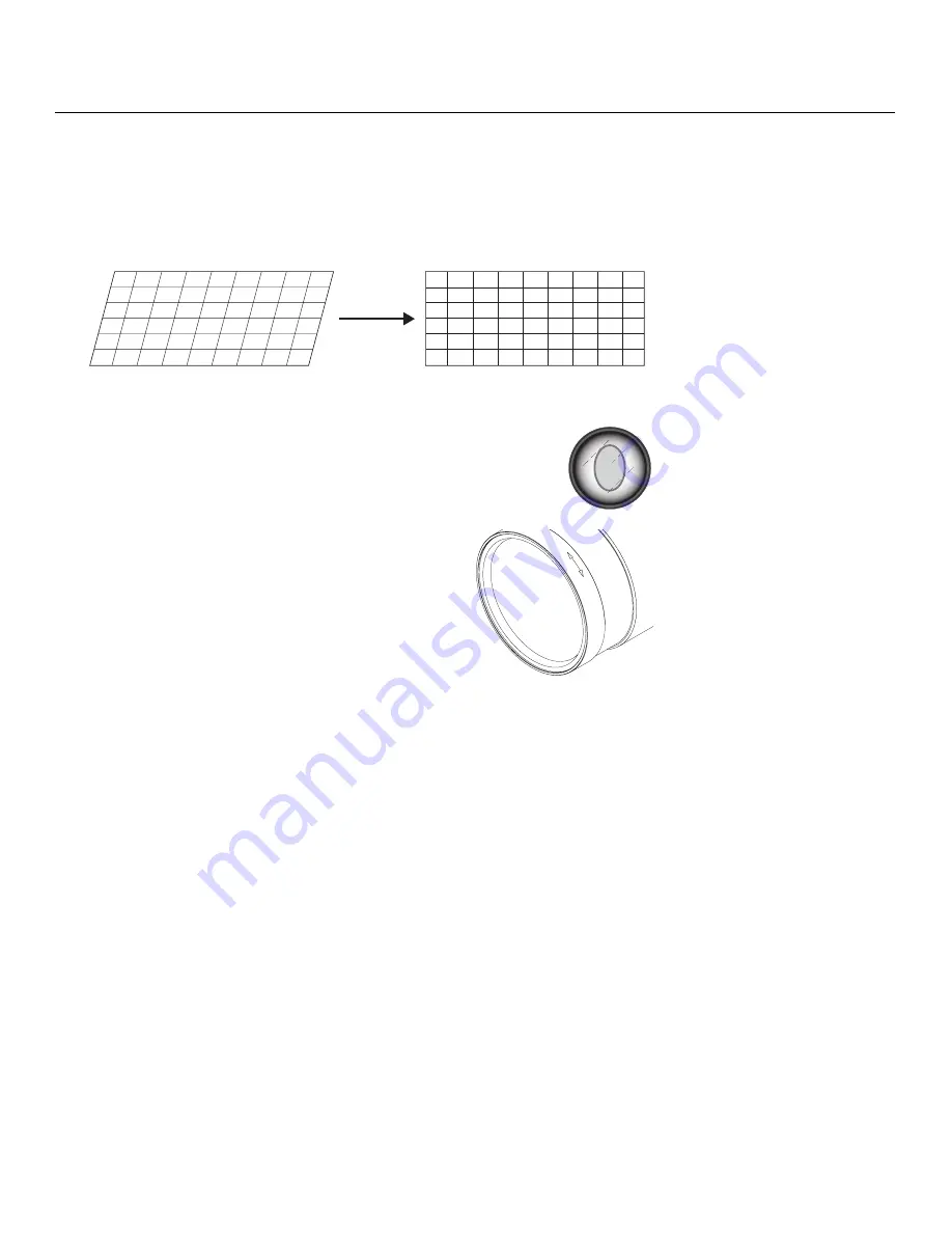
Adjusting the Geometry: 

1.

Input an anamorphic cross-hatch test pattern to the projector.

2.

Unscrew the Anamorphic Lens just enough to allow it to rotate freely.

3.

Grasp the lens by the center ring and rotate the lens until the image is properly 
anamorphic: 

4.

When the image geometry appears correct, tighten the Anamorphic 
Lens Set Screw (item #10) to secure the lens in place. (When viewed 
from the front, the rear opening on the anamorphic lens should 
appear as a tall, narrow oval.)


Focus: 

Finally, rotate the Focus Ring on the anamorphic lens 

to fine-tune the optical focus. 

Wrong Position

Correct Position

F

O

C

U

S

Содержание Model 70

Страница 1: ...SERIES 1080p DLP PROJECTORS Vision 70 Vision 70 CineWide Vision 70 CineWide with AutoScope 70 O W N E R S O P E R A T I N G M A N U A L ...

Страница 2: ......

Страница 3: ...over normal maintenance This Limited Warranty does not cover cabinets or any appearance items failure resulting from accident misuse abuse neglect mishandling misapplication faulty or improper installation or setup adjustments improper maintenance alteration improper use of any input signal damage due to lightning or power line surges spikes and brownouts damage that occurs during shipping or tran...

Страница 4: ...sponsibility to arrange for shipment of the product for repair These arrangements must be made through the selling Vidikron Dealer If this is not possible contact Vidikron directly for a Return Authorization number and shipping instructions Vidikron will return product transportation prepaid in the United States unless no product defect is discovered In that instance shipping costs will be the res...

Страница 5: ..._ ________________________________________ Model Purchased Date ____________________________________________________________________________________________________________ Serial Number ____________________________________________________________________________________________________________ Vidikron Authorized Dealer Name ________________________________________________________________________...

Страница 6: ...he 12V trigger only outputs DC 12V signal for triggering Do not connect to any other power input or output This could cause damage to this unit 10 Only use accessories specified by Vidikron 11 Keep the packing material in case the equipment should ever need to be shipped 12 Unplug this projector during lightning storms or when it will not be used for an extended period of time 13 The lamp becomes ...

Страница 7: ... Glance 5 Vision 70 Connector Panel 7 Built In Keypad 8 Vision 70 Remote Control 9 Remote Control Built In Keypad Functional Comparison 12 3 Installation 13 Remote Control 13 Notes on Batteries 13 Notes on Remote Control Operation 13 Quick Setup 14 Installation Considerations 15 Installation Type 15 Ambient Light 15 Throw Distance 16 Vertical and Horizontal Position 17 Vertical Lens Shift 17 Folde...

Страница 8: ... 31 Turning on the Power 31 Changing the OSD Language 32 Adjusting the Picture Orientation 32 Primary Lens Adjustments 32 Focus 32 Zoom 32 Vertical Lens Shift 32 Installing and Adjusting the CineWide Anamorphic Lens 33 Anamorphic Lens Installation and Adjustment Vision 70 CineWide 33 Anamorphic Lens Installation and Adjustment Vision 70 CineWide with AutoScope 36 4 Operation 43 Selecting Video Mem...

Страница 9: ...nce and Troubleshooting 63 Lamp Replacement 63 Troubleshooting Tips 64 6 Serial Communications 67 RS 232 Connection and Port Configuration 67 Serial Command Syntax 67 7 Specifications 71 Vision 70 Specifications 71 Vision 70 Dimensions 74 APPENDIX A Personalizing the ISF Splash Screen on the Vision 70 A 1 ...

Страница 10: ...Table of Contents x Vidikron Vision 70 Series Owner s Operating Manual P R E L I M I N A R Y Notes ...

Страница 11: ...Bottom View 23 3 9 HDMI DVI Source Connections 25 3 10 RGB Connections 26 3 11 Progressive Component Video Connections 27 3 12 Composite S Video and Component Video Connections 28 3 13 RS 232 Control System Connection 29 3 14 Connecting the 12 volt Trigger Output to the AutoScope Lens Motor 30 3 15 Connecting the 12 volt Trigger Output to Other Equipment 30 3 16 Standard Vision 70 Anamorphic Lens ...

Страница 12: ...List of Figures xii Vidikron Vision 70 Series Owner s Operating Manual P R E L I M I N A R Y Notes ...

Страница 13: ...of this and other Vidikron product manuals on line at www Vidikron com If You Have Comments About This Manual Vidikron welcomes your comments about this manual Send them to info vidikron com Textual and Graphic Conventions Text Conventions The following conventions are used in this manual in order to clarify the information and instructions provided Remote and built in keypad button identifiers ar...

Страница 14: ... significance They also provide supplemental information CAUTIONS alert users that a given action or omitted action can degrade performance or cause a malfunction WARNINGS appear when a given action or omitted action can result in damage to the equipment or possible non fatal injury to the user DANGER appears when a given action can cause severe injury or death Tip Note Caution WARNING DANGER If y...

Страница 15: ... and reduces noise levels The Vision 70 has been engineered to comply with Imaging Science Foundation ISF standards for maximum home theater image quality Vidikron s sophisticated parameters for white balance and color gamut control have also been implemented for precise balance of gray scale and color The Vision 70 incorporates Vidikron proprietary de interlacing technology that provides exceptio...

Страница 16: ...tection HDCP HDTV Compatible Parts List Your Vision 70 is shipped with the following items If any items are missing or damaged please contact your Vidikron dealer or Vidikron Customer Service at 888 4VIDIKRON Vision 70 DLP Projector Remote Control Unit and two 2 AAA size batteries AC Power Cords North America Europe Asia Source Connection Cables Composite Video S Video Component Video RGB DB15HD t...

Страница 17: ... at the sides pull it away from the projector and rotate it 180 degrees 2 TOP IR SENSOR 3 LAMP LED Indicates lamp status as follows Off during normal operation Red when the lamp has exceeded its usage life or developed a problem Flashes red when the fans are not working or the lamp cover is open 4 POWER STANDBY LED Indicates power status as follows Orange when the projector is in standby mode Flas...

Страница 18: ... turned off to indicate that the lamp is cooling down 5 TEMP LED Indicates fan status and internal temperature as follows Off during normal operation Red when internal temperature is too high Flashes red when the fans are not working or the lamp cover is open 6 INTAKE VENT 7 EXHAUST VENT 8 FRONT IR SENSOR 9 PROJECTION LENS Figure 2 2 Vision 70 Rear Bottom Side View 4 3 2 1 5 6 5 ...

Страница 19: ...ompartment 5 FRONT REAR ADJUSTERS Use these to adjust the projector height or projection angle 6 CEILING MOUNT HOLES Use these to attach the ceiling bracket to the projector 2 2 Vision 70 Connector Panel To access the connector panel press the door release button so it pops out Turn the knob clockwise or counter clockwise and pull gently on it to open the door Figure 2 3 shows the Vision 70 connec...

Страница 20: ... CONTROL PORT A female RJ 11 connector for interfacing with a PC or home theater automation control system 7 12 VOLT 250 mA TRIGGER OUTPUT 3 5 mm mini phono jack Connection for a 12 volt trigger controlled device This can be a retractable screen screen mask or the Vidikron CineWide with AutoScope system 8 COMP 2 RGB Five BNCs for connecting either RGB or component YPbPr high definition television ...

Страница 21: ...eries Owner s Operating Manual 9 P R E L I M I N A R Y 2 4 Vision 70 Remote Control Figure 2 4 shows the Vision 70 remote control and the paragraphs that follow describe its functionality Figure 2 4 Vision 70 Remote Control 4 2 6 9 1 3 5 7 8 10 ...

Страница 22: ...lect the Component 2 RGB input HDMI Press to select the HDMI input 3 Aspect Ratio Selection Buttons Use these buttons to select an aspect ratio directly as follows ANA Anamorphic For viewing 16 9 DVDs or HDTV programs in their native aspect ratio 4X3 Standard 4 3 Scales the input signal to fit 4 3 display mode in the center of the screen L BOX Letterbox For viewing LaserDisc movies or non anamorph...

Страница 23: ...djust settings or switch display patterns EXIT Press to save menu item setting s exit the current menu and return to the previous one ENTER Press to select a highlighted menu item or confirm a changed setting MENU Press this button to show or hide the on screen display OSD controls 6 0 9 Use these keys to enter menu passcodes 7 Picture In Picture PIP Picture By Picture PBP Controls PIP Press to ac...

Страница 24: ...nctional Comparison Figure 2 5 shows remote control buttons that are duplicated on the built in keypad Some functions such as power ON OFF are combined in one button on the built in keypad however the function is the same This user manual describes the functions based on the remote control Figure 2 5 Remote Control Built In Keypad Functional Cross Reference FOCUS 6 9 8 7 4 5 1 2 3 1 8 9 2 6 8 7 9 ...

Страница 25: ...e batteries to avoid damage from battery leakage Notes on Remote Control Operation Make sure that there is nothing obstructing the infrared beam between the remote control and the IR receiver on the projector If the effective range of the remote control decreases or it stops working replace the batteries with new ones The remote control may fail to operate if the infrared remote sensor is exposed ...

Страница 26: ... Mount the projector 24 4 Connect signal sources to the Vision 70 25 5 Connect external controller to RS 232 port optional 29 6 Connect 12 volt trigger output to AutoScope lens motor or other equipment optional 30 7 Apply power to the projector 31 8 Change the OSD Language optional 32 9 For rear screen and or ceiling mount installations select the proper picture orientation 32 10 Primary lens adju...

Страница 27: ...less vibrant Table 3 2 Projector Installation Options Advantages Considerations Front Screen Floor Mount Installation Easy to set up Can be moved or changed quickly Easy to access Shares floor space with audience Front Screen Inverted Mount ceiling Installation Does not take up audience space Projector is unobtrusive Projector cannot be accidentally moved Installation is more permanent Projector a...

Страница 28: ...he projector should be positioned from the screen in order to project a focused image large enough to fill the screen Figure 3 1 Estimating Throw Distance Table 3 3 gives the throw ratios for the Vision 70 Vision 70 CineWide and Vision 70 CineWide with AutoScope Table 3 3 Throw Ratios for the Vision 70 Series Projector Model Throw Ratio with Primary Lens Only Throw Range in inches with 72 6x40 8 i...

Страница 29: ...t is not possible to align the projector and screen as shown in Figure 3 2 you can use the projector s lens shift LENS controls to center the image on the screen Vertical lens shift is generally expressed as a percentage of the screen height as shown in Figure 3 3 Figure 3 3 Vertical Lens Shift EXAMPLE ONLY Height Projection Distance Ceiling Ceiling Installation Screen Height Floor Lens Center Pro...

Страница 30: ...n in Figure 3 4 The position of the projector and mirror must be accurately set If you are considering this type of installation contact your dealer for assistance Figure 3 4 Folded Optics Other Considerations Other considerations and tips that can help improve your installation Keep the ambient temperature constant and below 35 C 95 F Keep the projector away from heating and or air conditioning v...

Страница 31: ... proceed with Installing the Fixed CineWide Base Plate Vision 70 CineWide page 23 If you are installing a Vision 70 CineWide with AutoScope proceed as follows to install the AutoScope lens motor 1 Do not install the CineWide lens yet only the fixed CineWide base plate or AutoScope lens motor You will install the CineWide lens after you install the projector and adjust the primary lens 2 Some compo...

Страница 32: ... Exploded View Remove Projector Front Height Adjusters Place the projector upside down on a blanket or other soft surface Then remove the two height adjusters at the front of the projector by turning them counterclockwise until they come out 3 4 Screw Phillips Pan Head 10 32 x 1 2 10x 1 AutoScope Lens Motor 2 CineWide with AutoScope Ceiling Mount Adapter Projector Stand Right CineWide with AutoSco...

Страница 33: ...he projector up and around the AutoScope lens motor housing For floor installations where the projector is upright the adapters allow the projector to lie flat on the mounting surface Using six 6 each of the supplied 10 32 x 1 2 Pan Head Phillips screws item 2 and nylon spacers item 5 attach the AutoScope Ceiling Mount Adapters Projector Stands items 3 and 4 to the projector as shown in Figure 3 6...

Страница 34: ...3 7 Line up the mounting holes on the lens motor housing with those on the underside of the projector Secure the motor to the projector with the four remaining 10 32 x 1 2 Pan Head Phillips screws item 2 and nylon spacers item 5 Figure 3 7 AutoScope Lens Motor Installation After you have installed the AutoScope lens motor proceed with Mounting the Vision 70 on page 24 ...

Страница 35: ...r ceiling mount kit with those on the bottom of the projector 4 Secure the CineWide base plate and ceiling mounting plate if needed to the projector with the four M6x16mm screws and washers provided with the CineWide lens base plate See Figure 3 8 Figure 3 8 Vision 70 CineWide with Anamorphic Lens Base Plate and Ceiling Mounting Plate Bottom View The hole pattern on the CineWide base plate is iden...

Страница 36: ...closure on which the projector can rest A variety of materials can be used for this purpose for example rubber crutch tips or turntable feet Adjusting the Projector Height or Projection Angle If the screen is significantly higher or lower than the projector you can also tilt the projector at a slight angle In a ceiling installation you do this by adjusting the ceiling mount For a floor installatio...

Страница 37: ... the door release button so it pops out Turn the knob clockwise or counter clockwise and pull gently on it to open the door Connecting Source Components to the Vision 70 Connect your video sources to the Vision 70 as shown and described in the sections that follow HDMI DVI Connections See Figure 3 9 With an HDMI source use the included HDMI to HDMI cable with a DVI source use the included DVI to H...

Страница 38: ...top box to the COMP 2 RGB input see Figure 3 10 You can use the included DB15HD to 5 x BNC cable if your RGB source has a 15 pin VGA type connector Figure 3 10 RGB Connections The Vision 70 supports computer resolutions of 1024x768 800x600 and 640x480 Note S VID S VID S VID S VID DVD Player or HD Set Top Box Green Blue Red Horiz Vert Green Blue Red Horiz Vert Personal Computer ...

Страница 39: ... N A R Y Progressive Component Video Connections Connect your progressive component source DVD player or HD set top box to the COMP 2 RGB input as shown in Figure 3 11 Figure 3 11 Progressive Component Video Connections S VID S VID DTV or Progressive Component YPbPr Source Y Pb Pr ...

Страница 40: ...ite S Video Component Video Connections Use the included cables to connect your composite S Video and SD 480i component video sources to the Vision 70 as shown in Figure 3 12 Figure 3 12 Composite S Video and Component Video Connections S VID S VID DTV Source DVD Player VCR Satellite Receiver etc ...

Страница 41: ...telephone cable wired straight through For more information about using this connection refer to Serial Communications on page 67 Figure 3 13 RS 232 Control System Connection S VID S VID 1 2 3 4 5 7 8 9 6 D Sub 9 pin female RJ 11 Male RJ 11 to D Sub 9 pin Adapter not included 1 2 3 4 Yellow Yellow Red Red Black Green Green Black RS 232 Adapter Wiring D Sub 9 pin female 4 pin RJ 11 Function 2 2 Tra...

Страница 42: ...4 Connecting the 12 volt Trigger Output to the AutoScope Lens Motor If your home theater contains a retractable screen screen mask or other 12 volt trigger activated equipment use the cable supplied with the Vision 70 to connect it to the 12 volt trigger output as shown in Figure 3 15 Figure 3 15 Connecting the 12 volt Trigger Output to Other Equipment AutoScope Lens Motor Rear AC Input Power Swit...

Страница 43: ...the AutoScope lens motor The lens motor power switch is located next to the AC input see above 3 Turn on the main power switch at the rear of the projector The POWER LED lights orange The LAMP and TEMP LEDs light red briefly then go out 4 Press the ON button on the remote control to turn on the Vision 70 The POWER LED flashes orange to indicate that it is warming up 5 When the projector is ready f...

Страница 44: ...ange the picture orientation To do this 1 Press MENU on the remote control 2 Select Installation from the Main Menu and press ENTER 3 Select Picture Orientation from the Installation Menu and press ENTER 4 Choose Floor Rear Ceiling Front or Ceiling Rear to match the installation method 3 10 Primary Lens Adjustments The Vision 70 gives you a great deal of control over the picture size position and ...

Страница 45: ...n and Adjustment Vision 70 CineWide with AutoScope on page 36 If you are installing a standard Vision 70 CineWide continue with the next section AnamorphicLensInstallation and Adjustment Vision 70 CineWide The standard Vision 70 Anamorphic lens mount kit consists of everything shown in Figure 3 16 Some components shipped with your projector may differ slightly from what is shown in these instructi...

Страница 46: ...ite field on the screen 2 Ensure that the two Pitch Y Adjustment Screws are loose enough to allow vertical movement of the lens assembly 3 Slowly move the anamorphic lens into place so that there are no shadows on the top or bottom of the screen 4 When the height is properly set tighten the Pitch Y Adjustment Screws to secure the lens in place Adjusting the Pitch Angle Next angle the lens to even ...

Страница 47: ... Yaw Loosen the Yaw Z Adjustment Levers to allow the lens to pivot freely from side to side Then angle the lens to even out any left right pincushion distortion There may be some pincushion distortion even after the lens is properly adjusted especially at shorter throw distances If this is the case Vidikron recommends that you slightly over scan the image into the screen frame area to mask the dis...

Страница 48: ...consists of everything shown in Figure 3 17 Some components shipped with your projector may differ slightly from what is shown in these instructions Figure 3 17 Anamorphic Lens Mounting Assembly Exploded View 2 3 4 6 7 8 5 1 9 Pitch Adjustment Yoke for Lens Height Y Adjustment T Screw 2x T Screw 2x Pitch Adjustment Anamorphic Lens Holder 1 4 20 Hex Bolt 2x and Washer 2x AutoScope Carriage Plate Ya...

Страница 49: ...ic Lens Holder to the plate using the Hex Bolts Washers item 6 and Yaw X Adjustment Levers that you removed in Step 1 4 Use the Lens Mounting Screws to attach the Lens Adapter Ring item 1 to the Pitch Adjustment Yoke item 2 see Figure 3 18 Use the round threaded holes on the yoke 5 Use the Height Y Adjustment T Screws item 3 Pitch Adjustment T Screws item 4 and T Nuts item 9 to attach the Pitch Ad...

Страница 50: ...ervice menu passcode when prompted and press ENTER again Then press MENU on the remote control 4 Select Screen Trigger Mode from the Service menu 5 Set the Screen Trigger Mode to Trigger This enables the lens motor to move the anamorphic lens into position in front of the primary lens when the Cinema or Cinema Fill aspect ratio is selected 6 Select the Cinema or Cinema Fill aspect ratio to move th...

Страница 51: ...he Pitch Adjustment T Screws directly below the Height Y Adjustment T Screws on either side of the lens to allow it to pivot freely Then adjust the anamorphic lens angle so that the projected image is rectangular The anamorphic lens will almost always be angled with respect to the projector this is normal Once the proper lens angle has been set firmly tighten the Pitch Adjustment T Screws to secur...

Страница 52: ...the Yaw X Adjustment Levers to allow the lens to pivot freely from side to side Then angle the lens to even out any left right pincushion distortion Once the proper lens angle has been set firmly tighten the Yaw X Adjustment Levers to secure the lens in place Anamorphic Lens Top View Wrong Position Correct Position ...

Страница 53: ...y 3 Grasp the lens by the center ring and rotate the lens until the image is properly anamorphic 4 When the image geometry appears correct tighten the Anamorphic Lens Set Screw item 10 to secure the lens in place When viewed from the front the rear opening on the anamorphic lens should appear as a tall narrow oval Focus Finally rotate the Focus Ring on the anamorphic lens to fine tune the optical ...

Страница 54: ...Installation 42 Vidikron Vision 70 Series Owner s Operating Manual P R E L I M I N A R Y Notes ...

Страница 55: ...urn on the Vision 70 it switches to the last selected input and looks for a valid signal Use these buttons on the remote control to select an input source directly 4 4 Using Picture In Picture Picture By Picture PIP PBP For PIP and PBP purposes there are two groups of inputs separated by their display modes Video SD group Video S Video and Component 1 inputs Graphic HD group HDMI and Component 2 R...

Страница 56: ...ntrol to highlight it Press ENTER or to confirm your selection Use the arrow buttons to select menu items or change settings Press EXIT to return to the previous menu Press MENU to turn off the OSD menu When the Main Menu is displayed pressing EXIT also turns off the menu The Vision 70 OSD menus are arranged hierarchically as shown in Figure 4 1 Depending on the selected input source and signal ch...

Страница 57: ...Day Splash Screen Timer 5 6 7 60 seconds ISF Enable On Off Return to User OSD Picture Adjust Brightness 0 60 Contrast 0 32 Color 0 64 Tint 0 30 Sharpness 14 0 25 Color Temp 0 1 2 5 Color Select Standard NTSC HDTV or PAL Image Option Input Select Video S Video Component 1 Component 2 RGB HD or HDMI Aspect Ratio Anamorphic 16 9 Standard 4 3 Letterbox IntelliWide Cinema Cinema Fill Vision 70 CineWide...

Страница 58: ...optimal video performance and has implemented a training program for technicians and installers to use these standards to obtain optimal picture quality from Vidikron video display devices Accordingly Vidikron recommends that setup and calibration be performed by an ISF certified installation technician All signal types require separate processing Therefore you need to calibrate each input separat...

Страница 59: ...er listed here Brightness On your external test pattern source select a PLUGE pattern PLUGE is an acronym for Picture Line Up Generation Equipment Figure 4 2 shows a typical PLUGE pattern Figure 4 2 Typical PLUGE Pattern for Adjusting Brightness PLUGE patterns vary but generally consist of some combination of black white and gray areas against a black background The example above includes two vert...

Страница 60: ... menu and press ENTER Adjust the contrast to a point just below which the white rectangle starts to increase in size Color Saturation On your external test pattern source select a color bar pattern like the one shown in Figure 4 4 Figure 4 4 Typical Color Bar Pattern for Adjusting Color Saturation and Tint Brightness and contrast controls are interactive A change to one may require a subtle change...

Страница 61: ...n of the image When tint is decreased the image appears redder when it is increased the image appears greener To set the tint select Tint from the Picture Adjust menu and press ENTER While looking at the color bar pattern through a blue filter adjust the tint level until the cyan and magenta color bars on either side of the green bar appear to be a single shade of blue Like the brightness and cont...

Страница 62: ...rpness setting to eliminate them Figure 4 5 Typical Test Pattern for Adjusting Sharpness Color Temp The Vision 70 has six memory settings for Color Temperature Four of these settings are factory set to default as follows 0 Original lamp color temperature 1 5400 kelvins 2 6500 kelvins 3 8500 kelvins 4 Custom 5 Custom Custom 4 and 5 memory are installer adjustable and can be used to create custom se...

Страница 63: ...ent 1 Component 2 RGB HD or HDMI Then press ENTER to confirm Aspect Ratio To change the aspect ratio size and shape of the projected image select Aspect Ratio from the Main Menu and press ENTER Select the appropriate aspect ratio for your screen size and the type of program material being viewed refer to Table 4 1 You must enter a passcode in order to enter the Service menu Note Image Option Input...

Страница 64: ... video cassettes Letterbox LBOX Letterbox mode scales zooms in on a 4 3 image linearly by the same amount on all sides to fill a 16 9 display Letterbox is best suited for viewing LaserDisc movies or non anamorphic DVDs on a 16 9 screen IntelliWide I WIDE IntelliWide scales a 4 3 image NON linearly more on the sides than in the center to fit a 16 9 screen On a 2 35 1 screen the image is centered be...

Страница 65: ... make will be Cinema CINEMA Select Cinema to view 2 35 source material in its native aspect ratio With a 16 9 screen and a non CineWide projector no anamorphic lens the upper and lower portions of the screen are masked but the geometry of the active image area is unchanged With a 2 35 1 screen and a CineWide equipped projector the projector scales the 2 35 1 image so that the active image area fil...

Страница 66: ... the Blue Enable Off or On This feature removes all red and green color information from the image simulating a blue filter and is useful for color calibrating the projector or other video components Save Settings When you have finished making your adjustments select Save Settings to store the settings for the current input in the Custom 1 memory location Load Saved Settings To recall stored custo...

Страница 67: ...he or button to set the OSD Timer This timer controls how long the menus remain on screen after selecting them Select from 0 to 60 seconds in 3 second increments When you set the OSD Timer to 0 the menus remain on screen until you hide them by pressing MENU PIP PBP Setup Select PIP PBP Setup from the Installation menu to change the PIP PBP settings PIP PBP Enable Press the or button to select PIP ...

Страница 68: ...o do this is to use a test pattern consisting mostly of solid white areas such as an 80 IRE window pattern If the white areas contain traces of red green or blue decrease the Gain for that color Offset Use the Offset controls in the White Balance sub menu to correct color imbalances in the dark areas of the image A good way to do this is to use a test pattern consisting mostly of dark gray areas s...

Страница 69: ...t older television sets may not display the outer edges of the broadcast picture area Over scan effectively trims away these inactive outer edges and enlarges the remaining portion of the image to fill the display area Use the on screen slidebar to select the desired amount of over scan For HDTV DVDs and other video sources Image Over Scan is generally not necessary or desirable Video Black Level ...

Страница 70: ...rojector s cooling fan Mode In most cases the default Fan Control Mode Auto Normal will maintain the correct operating temperature If the lamp frequently turns off due to overheating or in certain high altitude operating environments you may need to change this setting to Auto Hi Altitude or Manual Fan Speed If you set the Fan Mode to Manual select Fan Speed and use the on screen slidebar to adjus...

Страница 71: ...te sends that code instead of the primary IR code To simultaneously change the secondary IR code and synchronize that remote with a projector point the remote at the projector then press and hold and simultaneously for five seconds The Remote Control edit window shown at left appears Type a new two digit code The procedure for changing the secondary IR code on the remote only is the same except th...

Страница 72: ...46 Exit the Picture Adjust menu when finished 6 Select White Balance from the ISF Calibration menu Adjust the grayscale as required refer to White Balance on page 56 7 From the White Balance menu select Save Color Temp 4 or Save Color Temp 5 depending on your selection in Step 3 and press ENTER 8 From the ISF Calibration menu select Save ISF Settings and choose Save ISF Night to store your setting...

Страница 73: ...ct ISF Enable from the ISF Calibration menu to control the display of the ISF logo on the Vision 70 splash screen upon power up You can personalize the Vision 70 splash screen with the projector owner s name and or the installer s name For instructions refer to Appendix A Return to User OSD To exit the ISF Calibration menu use the up or down arrow keys to highlight Return to User OSD and press ENT...

Страница 74: ...Operation 62 Vidikron Vision 70 Series Owner s Operating Manual P R E L I M I N A R Y Notes ...

Страница 75: ...proximately 45 minutes prior to removing the lamp assembly for replacement 2 Remove the three screws from the lamp cover 3 Remove the lamp cover 4 Remove the two lamp assembly mounting screws 5 Grasp the lamp assembly handle and pull gently removing the lamp module from the projector housing 6 Install the new lamp module and replace the two screws 7 Replace the lamp cover at the top first and secu...

Страница 76: ...ision 70 completes its cool down POWER LED lights solid orange The remote control does not work correctly The batteries have run out Replace the batteries The projector is on and OSD menus appear but there is no video image on screen Incorrect source selection Source component is not turned on Source component is connected incorrectly or not at all Select the correct source Turn on the source Chec...

Страница 77: ...lashing red The lamp cover is open Fans are not working properly Close the lamp cover Please contact your Vidikron dealer for assistance LAMP LED lights solid red The lamp has failed or exceeded its usage life Replace the lamp with a new one TEMP LED lights solid red Vision 70 internal temperature is too high Power off the Vision 70 and allow it to cool down Ensure that the intake and exhaust vent...

Страница 78: ...Maintenance and Troubleshooting 66 Vidikron Vision 70 Series Owner s Operating Manual P R E L I M I N A R Y Notes ...

Страница 79: ...You should see a command prompt in the terminal window 5 Type a command from among those listed in Table 6 1 and press Enter For example to change the aspect ratio to Letterbox type x063x Enter 6 2 Serial Command Syntax Serial commands to the Vision 70 take the following form Commands are in ASCII format Commands are not case sensitive X001X and x001x are equivalent A carriage return MUST follow e...

Страница 80: ...re image settings from ISF Day x049x Load default of current source x051x Single source full screen x052x PIP graphics on video x053x PIP video on graphics x054x PBP graphics by video x055x PBP video by graphics x056x PIP increase sub window size x057x PIP decrease sub window size x058x Set PIP PBP active window x061x Anamorphic 16 9 aspect ratio x062x Standard 4 3 aspect ratio x063x Letterbox asp...

Страница 81: ...o S Video input x133x Switch to RGB HD input x134x Switch to DVI input HDMI x135x Switch to Component 1 input x136x Switch to Component 2 input x156x Background Color Grey x157x Background Color Blue x158x Background Color White x161x Un freeze Image x162x Freeze Image x181x Toggle Blue Image on off x261x Vertical Lens Shift Up incremental x262x Vertical Lens Shift Down incremental x263x Zoom Out ...

Страница 82: ...N A R Y x282x Vertical Lens Shift Max Down x283x Zoom Max Out x284x Zoom Max In x285x Focus rotate lens to right full range x286x Focus rotate lens to left full range x287x Aperture Control Full On open x288x Aperture Control Full Off closed Table 6 1 Serial Commands continued Code Function ...

Страница 83: ...amorphic IntelliWide Cinema Cinema Fill Video Standards NTSC PAL SECAM DTV Compatibility 480p 576p 720p 1080i 1080p Scan Frequency Horizontal 15 80 kHz Vertical 50 100 Hz Picture Size 16 9 Screen Recommended Width 72 in 1 83 m to 96 in 2 44 m Capable of screen widths between 48 in 1 22 m and 200 in 5 08 m Throw Distance Factor x Screen Width Refer to Table 3 3 Horizontal and Vertical Lens Shift Ho...

Страница 84: ...ations Light Output 451 to 589 ANSI Lumens Contrast Ratio 200 1 to 230 1 These specifications are obtained by calibrating the projector as described above for CSMS measurements Industry Standard Specifications Light Output 1290 ANSI Lumens Contrast Ratio 1550 1 to 3250 1 These are typical projector brightness and contrast specifications found in most companies sales literature Vidikron includes th...

Страница 85: ...gulatory Approvals Complies with FCC CE C Tick Limited Warranty Projector Two 2 years parts and labor from the date of delivery to the end user Lamp 1000 hours or six 6 months whichever comes first Specifications are subject to change without notice Table 7 1 Vision 70 Specifications continued ...

Страница 86: ...ensions Figure 7 1 shows the Vision 70 dimensions Figure 7 1 Vision 70 Dimensions with Optional Fixed Anamorphic Lens 14 9 in 379 68 mm 4 1 in 103 89 mm 17 3 in 440 00 mm 13 0 in 330 00 mm 11 0 in 280 25 mm 22 0 in 560 51 mm 4 4 in 110 80 mm 8 0 in 203 00 mm 8 8 in 222 50 mm 18 9 in 480 00 mm 6 9 in 175 00 mm ...

Страница 87: ...ote control Then select Splash Screen Timer from the ISF Calibration menu 4 Use the left or right arrow buttons to set the Splash Screen Timer This timer controls how long the startup Vidikron ISF logo image stays on screen after you turn on the projector The range is from 5 to 60 seconds in 1 second increments For this procedure set it to 30 seconds and press EXIT 5 In the HyperTerminal window at...

Страница 88: ...g the ISF Splash Screen on the Vision 70 A 2 Vidikron Vision 70 Series Owner s Operating Manual P R E L I M I N A R Y 9 Power cycle the projector to see the change CALIBRATED FOR John Doe By Tinh Ho CUSTOM BUILT BY ...

Страница 89: ......

Страница 90: ...Vidikron 2900 Faber Street Union City CA 94587 510 324 5900 Fax 510 324 5905 1 888 4 VIDIKRON www vidikron com SERIAL NUMBER RUMA 011225 rev 03 20 07 v1 2 ...

Отзывы: