background image

STH-DCSG


U

SER

M

ANUAL


©

2005


V

IDERE 

D

ESIGN


2 Quick 

Start 

The STH-DCSG/-C normally comes assembled with the lenses mounted.  If 
you need to change the lenses, or if you are supplying your own, please see 
Section 6.1. 

To set up and test the STH-DCSG/-C, you will need the following: 

1.


Pair of C-mount lenses, for 1/2” or larger imager (normally 
included and mounted with the STH-DCSG/-C kit). 

2.


Host computer with an IEEE 1394 PCI (desktop) or PCMCIA 
(laptop) card, OHCI compliant; or a built-in IEEE 1394 port. 

3.


IEEE 1394 6-pin to 6-pin cable. 

4.


Small Vision System installed on the host computer. 

Install the IEEE 1394 host card, if necessary, according to the directions in 
Section 4.1.  Install the Small Vision System software (see Section 4.2).   

If the lenses are not mounted on the device, follow the directions in Section 
6.1 for installing them. 

Plug one end of the IEEE 1394 6-pin video cable into the 1394 jack on the 
back of the STH-DCSG/-C, and the other into an IEEE 1394 port on the 
host PC.   

Note: The STH-DCSG draws power from the IEEE 1394 bus.  PCI 
cards, or built-in ports for desktop machines, normally supply this 
power.  For PCMCIA cards (PC Cards), and laptops with a built-in 
port, no power is available.  In this case, external power must be 
supplied – see Section 5.3. 

The PC operating system will normally recognize the STH-DCSG, and 
install the correct system drivers.  Please see the Videre support web pages 
(

www.videredesign.com/support.htm

) for specific information about 

installation for your OS.  At this point, you should check to see that the 
STH-DCSG has been recognized by the system. 

Start the SVS main program, 

smallv(.exe)

 or 

smallvcal(.exe)

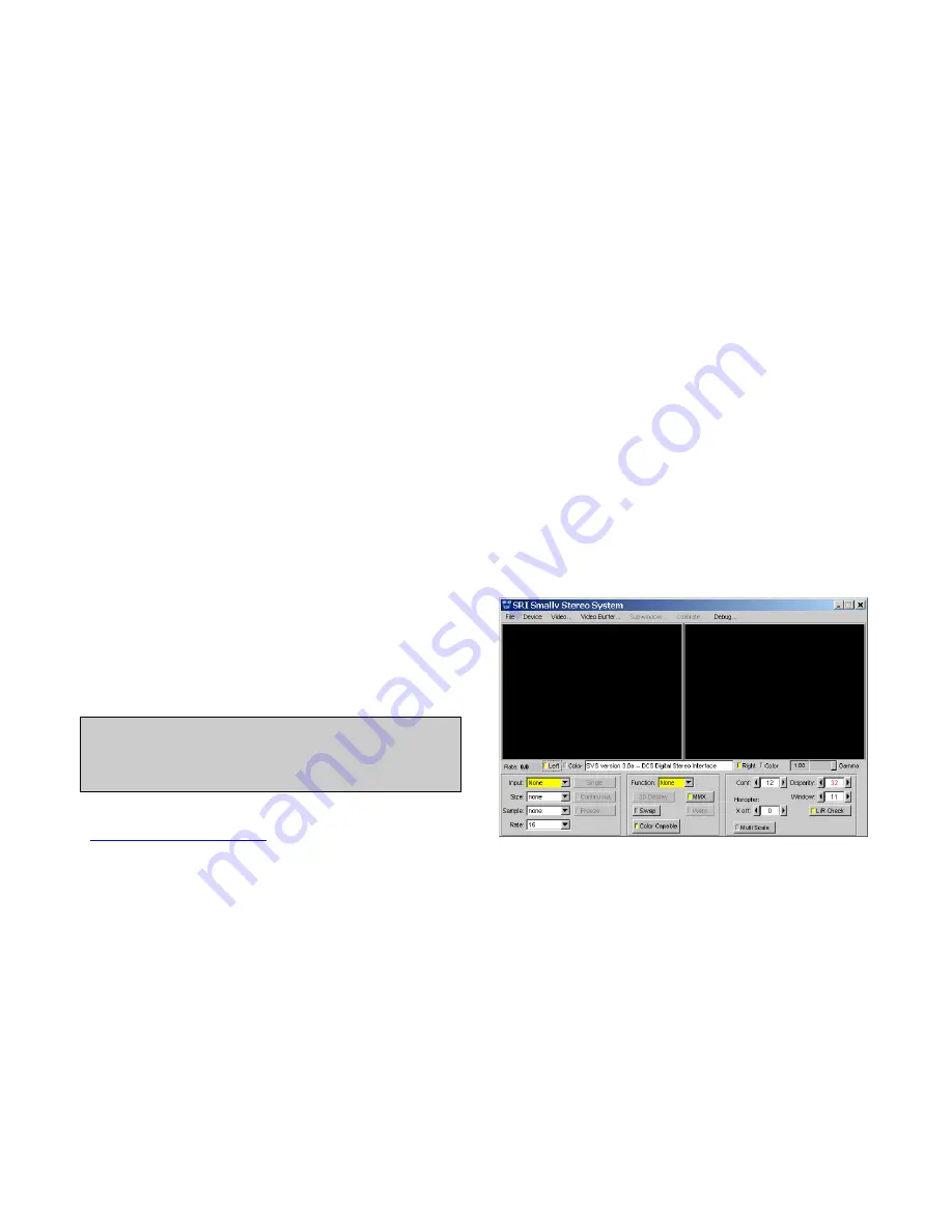
on the host computer.  You should see a screen as in Figure 2-1.  The 
message window should indicate that the “DCS Digital Stereo Interface” is 
present.  If not, go back to software installation (Section 4.2), and follow 
the instructions for configuring the correct capture library. 

Pull down the Input chooser, and select the 

Video

 option.  If everything 

has been set up correctly, the SVS interface will recognize and configure 
the stereo head, and a success message will appear in the info text window.  
If not, the Input chooser will go back to 

None

, and an error message will 

appear in the info window.  Please see Section 4 for troubleshooting. 

To view stereo video, press the 

Continuous

 button.  Left and right 

images should appear in the application windows.  If the message “Image 
timed out” appears, then there is a problem with the IEEE 1394 drivers; 
please see Section 4.  If the images are too light or too dark, you can open 
the manual iris of the cameras, or change the exposure and gain settings 


Figure 2-1  SVS main program window. 

Содержание STH-DCSG

Страница 1: ...STH DCSG USER S MANUAL 2005 VIDERE DESIGN 1 STH DCSG C Stereo Head User s Manual April 2005 2005 Videre Design...

Страница 2: ...IEEE 1394 Cable 13 5 2 IEEE 1394 Host Interface 13 5 3 Supplying Power 13 6 Lenses 15 6 1 Locking Lenses 15 6 2 C and CS Mount Lenses 15 6 3 Changing Lenses 15 6 4 Cleaning the Imagers 15 6 5 Imager...

Страница 3: ...e 11 Figure 5 1 External power supply connections 14 Figure 6 1 Range resolution in mm as a function of distance 16 Figure 7 1 Video Parameters dialog 18 Figure 7 2 Frame size and sampling controls 19...

Страница 4: ...to the STH DCSG C please see the STH DCSG VAR C manual for more information SRI s Small Vision System SVS software has an interface to the STH DCSG C and is included with each stereo head You can sim...

Страница 5: ...s high sensitivity the STH DCSG allows for very short exposure times even under moderate lighting conditions So it is appropriate for high motion applications such as outdoor robotics motion capture e...

Страница 6: ...be supplied see Section 5 3 The PC operating system will normally recognize the STH DCSG and install the correct system drivers Please see the Videre support web pages www videredesign com support ht...

Страница 7: ...e menu A more complete description of the video capture program is in Section 7 The SVS programs are described in the SVS User s Manual and the SVS Calibration Addendum documentation that comes with t...

Страница 8: ...de only that is each line is output in succession from the full frame The maximum video rate is 12 megapixels per second from each imager The imagers are synchronized to a common clock so that the cor...

Страница 9: ...oduce a smaller image with improved noise characteristics 3 3 50 Hz Operation Indoor lighting especially from fluorescent fixtures can oscillate at the frequency of the electrical supply If the image...

Страница 10: ...o is determined by the maximum bandwidth of the bus for isochronous transfers 32 MB s This rate cannot be exceeded by the combined video streams on the bus Table 2 shows the bandwidth requirements for...

Страница 11: ...Section 5 for information about cabling and power for the IEEE 1394 bus 4 1 2 Linux Hardware and Driver Installation Linux kernels 2 4 or 2 6 kernels are required for operation Please see the Videre D...

Страница 12: ...alibration libraries are not included the only way to run the SVS calibration procedures is through the smallvcal exe application smallv exe is a GUI based application that allows the user to exercise...

Страница 13: ...be added by installing a 1394 PCI card or PCMCIA card for laptops 1394 PCI cards have 6 pin ports and supply power PCMCIA cards do not have the capability of supplying power and come with an adapter f...

Страница 14: ...5 1 External power supply connections On the left is power supplied to a PC Card with a power port On the right power is supplied through a hub with a power port Power should be 7 to 16 VDC at 1 5 W...

Страница 15: ...older or lens threads Once the threads are engaged continue screwing it on until it seats firmly You can snug it down but do not tighten it excessively since this can damage the lens and the lens hold...

Страница 16: ...ution comes with it 6 8 Range Resolution Range resolution is the minimum distance the stereo system can distinguish Since stereo is a triangulation operation the range resolution gets worse with incre...

Страница 17: ...SER S MANUAL 2005 VIDERE DESIGN 17 Lens focal length Horizontal FOV Vertical FOV 2 8 mm 69 deg 54 deg 4 0 51 40 8 0 27 20 16 14 10 Table 3 Horizontal and vertical field of view for different lens foca...

Страница 18: ...rmation is sampled at a lower resolution than a similar non colorized camera samples monochrome information In general a color camera has about the spatial resolution of a similar monochrome camera Th...

Страница 19: ...r the STH DCSG C devices In manual mode the user program sets the exposure and gain The exposure and gain are based on a 0 to 100 scale Here are some tips for setting exposure and gain In general keep...

Страница 20: ...me size and sampling setting affect the output image Explicit control over the sampling mode is accomplished with the SetSample function from the SVS API The first two lines of the table are for full...

Страница 21: ...ice is downloaded and stored in the device and will cause 50 Hz operation every time the STH DCSG is accessed To change back to 60 Hz uncheck the box and again save it to the device It is also possibl...

Страница 22: ...STH DCSG USER S MANUAL 2005 VIDERE DESIGN 22 8 Interface Software API Please see the Small Vision System manual for information about the software API for capturing and saving images...

Страница 23: ...hysical Dimensions and Mounting Diagram The diagram below shows the physical dimensions for the STH DCSG C The larger hole is threaded for a 20 machine screw standard tripod mounting screw The two sma...

Страница 24: ...125 6 5 12 5 25 50 Hz Max 30 Hz at 640x480 Exposure 1 line time to full frame Gain 0 12 dB 1x 4x Sensitivity 4 8 V lux sec monochrome S N 60 dB no gain Power 1 W Synchronization Internal pixel locked...

Страница 25: ...STH DCSG USER S MANUAL 2005 VIDERE DESIGN 25 10 2 Imager Response Color 10 3 Imager Response Monochrome...

Страница 26: ...STH DCSG USER S MANUAL 2005 VIDERE DESIGN 26 10 4 Filter Transmittance...

Страница 27: ...hnical support please contact Videre Design by email or FAX Videre Design 865 College Avenue Menlo Park CA 94025 Fax 650 323 3646 Email support videredesign com Technical information about stereo algo...

Отзывы: