EN - English - I
nstruc
tion manual
4
MNVKVIPNX_1744_EN
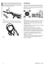
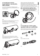
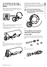
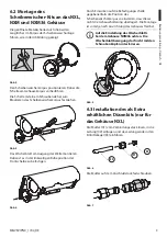
Unscrew one of the 2 fastening screws (01) of the
sunshield on the front part of the housing. Insert the
pipe (02) in the clip (03) and fasten everything with
the screw (01) and washer (04).
01
04
03
02
Fig.
8
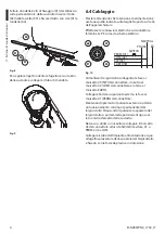
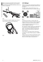
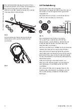
To adjust the jet, orientate the nozzle towards the
glass of the housing and connect the delivery pipe.
Fig.
9
6.4 Wiring
Pay attention the power supply voltage used is that
indicated on the plate on the back of the equipment.
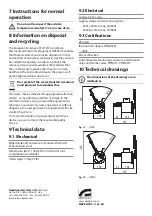
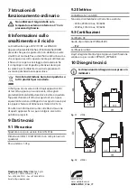
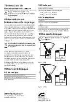
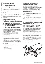
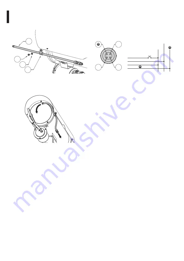
Electrically connect the female connector 3+PE as in
the wiring diagram.
PHASE
NEUTRAL
SWITCH
PERM (01)
COM (02)
SW (03)
EARTH
01
02
03
Fig.
10
Power the wiper by connecting the phase to terminal
03 (SW) of the connector, the neutral to terminal
02 (COM) of the connector and the earthing to the
EARTH terminal.
Using an outer button, connect the phase to terminal
01 (PERM) of the connector.
Having pressed the outer button, continuous
(permanent) functioning of the wiper is obtained.
Releasing the button, the blade on the wiper goes to
the stand-by position on the left of the housing glass.
If a receiver is used, connect terminal 03 of the
connector to the SW output of the receiver, 01 to
PERM and 02 to COM.
Connect the water supply system tube to the sprayer
nozzle of the wiper blade and fasten it with the
plastic clip supplied.
Содержание VIPNX
Страница 2: ......

