Victron energy SBP-100 Скачать руководство пользователя страница 10

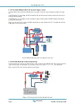
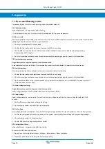
3.3.5. Two Smart BatteryProtects for load and charger control

It is also possible to have several Smart BatteryProtect in one system, for example, to control chargers and loads at the same
time.

If the BMS signals a cell undervoltage, the SBP responsible for the load will disconnect the load from the battery to protect the
battery from further discharge.

If the BMS signals a cell overvoltage or too low temperature to charge the lithium battery, the SBP will disconnect the charger
from the battery immediately.

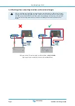
Please also note the correct connection of the SBPs: always follow the current flow from IN to OUT. The positive terminal of the
charger goes to the IN input of the SBP.

DC loads

SBP-65 charge

SBP-65 load

Two Smart BatteryProtects take control of a charger and a load circuit

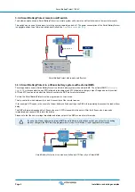
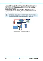
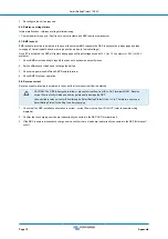
3.3.6. Smart BatteryProtect Alarm output wiring

The alarm output can be wired e.g. to an LED, a buzzer or a relay. For this, the Smart BatteryProtect must be programmed in the
respective mode because of slight differences in the behavior. See also the section 

Operation modes [9]

 for more details.

Make sure that the LED, buzzer and relay match the system voltage.

DC loads

LED

Buzzer

Relay

Wiring an LED, Buzzer or Relay to the Smart BatteryProtect output

Smart BatteryProtect 12/24V

Page 8

Installation and wiring examples

Содержание SBP-100

Страница 1: ...Smart BatteryProtect 12 24V 12 24V 65A 12 24V 100A 12 24V 220A rev 00 08 2022 ENGLISH...

Страница 2: ...m system with external BMS and load disconnect output 7 3 3 5 Two Smart BatteryProtects for load and charger control 8 3 3 6 Smart BatteryProtect Alarm output wiring 8 4 Operation and programming 9 4...

Страница 3: ...ared to the BatteryProtect the Smart BatteryProtect can be conveniently programmed via Bluetooth and our VictronConnect app or the PROG pin to GND pin method All necessary parameters can be set in thi...

Страница 4: ...ooth on This is important in case of Li ion batteries especially after low cell voltage shutdown Over voltage protection To prevent damage to sensitive loads due to over voltage The load is disconnect...

Страница 5: ...otection of the SBP will be activated if you try to directly connect loads with capacitors for example inverters or inverter chargers on their DC inputs For that use case please use the SBP to control...

Страница 6: ...erter charger via a SBP you must use the SBP to control the inverter or inverter charger via its remote port See example below Note that the image shown below is an example for all BatteryProtect mode...

Страница 7: ...the load after 90 seconds automatically DC loads Smart BatteryProtect in a simple system with wire loop between L and H input factory default The same example below This time the switch is wired betw...

Страница 8: ...ly controls the SBP via its remote terminal For this the Smart BatteryProtect must be programmed to Li ion mode The dry contact is wired between the L and H connectors of the remote terminal If for ex...

Страница 9: ...gh when there is an actual low cell voltage and the SBP will disconnect the load and remains off for 30 seconds even if it receives a restart signal H becomes high again within this period After this...

Страница 10: ...of the SBPs always follow the current flow from IN to OUT The positive terminal of the charger goes to the IN input of the SBP DC loads SBP 65 charge SBP 65 load Two Smart BatteryProtects take contro...

Страница 11: ...SBP will disconnect the load after 90 seconds and the relay will disengage In case of over voltage the load will be disconnected immediately and the alarm output will remain inactive Overvoltage trip...

Страница 12: ...t to set the restart voltage 9 Click on the 3 dots in the top right corner and then on Product info 10 In the Product info menu the PIN code can be changed a custom name can be set and Bluetooth can b...

Страница 13: ...0V 3 11 25V 22 5V 13 25V 26 5V 4 11 5V 23 0V 13 8V 27 6V 5 10 5V 21 0V 12 8V 25 6V 6 11 5V 23 0V 12 8V 25 6V 7 11 8V 23 6V 12 8V 25 6V 8 12 0V 24 0V 13 0V 26 0V 9 10 0V 20 0V 13 2V 26 4V User defined...

Страница 14: ...f switch to the positive supply of the BMS for this purpose Similarly if a system shutdown occurred due to low cell voltage the SBP will remain disengaged for 30 seconds even if it receives a re engag...

Страница 15: ...nce in a residential installation This equipment generates uses and can radiate radio frequency energy and if not installed and used in accordance with the instructions may cause harmful interference...

Страница 16: ...oad on alarm output 50mA short circuit proof Load disconnect delay 90 seconds immidiate if triggered by a BMS Load reconnect delay 30 seconds Default thresholds Disengage 10 5 V or 21 V Engage 12 V or...

Страница 17: ...t draw does not exceed the SBP current rating 2 Check for loose high resistance connections and ensure that appropriate gauge wiring is used in the installation 3 Do not install the SBP unit in a loca...

Страница 18: ...ween BMS and SBP Remote terminal 4 Check BMS for proper operation E8 Reverse current Reverse current protection is activated in the event that reverse current flow is detected CAUTION The SBP is desig...

Отзывы: