


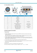


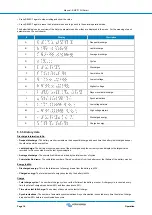


3.4. Connections overview
#
Name
Terminal type
A
Display
-
B
Setup button
-
C
Down button
-
D
Up button
-
E
Select button
-
F
RJ12 connector
RJ2 terminal
G
Buzzer
-
H
Programmable relay connector
Push connector
I
VE.Direct connector
VE.Direct terminal
J
Negative battery connection
M10 bolt
K
Positive battery connection
M10 ring terminal
M
Negative load connection
M10 bolt
N
Fuse holder with fuse
-
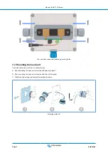
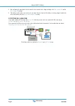
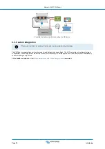
3.5. Basic electrical connections
Connection procedure:
1. Remove the fuse.
2. Connect the negative battery terminal to the M10 bolt on the "BATTERY" side of the shunt. Tighten the shunt bolt with a
maximum torque of 21Nm.
Note that there should be no other connections on this side of the shunt or on the negative battery terminal. Any loads or
chargers connected here will be excluded from the battery state of charge calculation.
3. Connect the negative of the electrical system to the M10 bolt on the "LOAD" side of the shunt. Tighten the shunt bolt with a
maximum torque of 21Nm. Make sure that the negative of all DC loads, inverters, battery chargers, solar chargers and other
charge sources are connected “after” the shunt.
4. Connect the M10 eye terminal of the red cable with the fuse to the positive terminal of the battery.
5. Connect the shunt to the head unit using the RJ12 cable. Plug one side of the RJ12 cable into the shunt RJ12 terminal and
the other side of the cable into the RJ12 terminal on the rear of the head unit.
6. Replace the fuse.
The battery monitor is now powered up. The display is active, and Bluetooth is active.
In order to be fully functional, the battery monitor needs to be configured; see the
chapter.
Manual - BMV-710H Smart
Page 7
Installation


