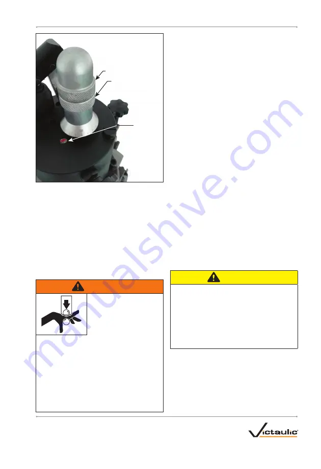
Locking Nut
Depth Adjuster Nut
Reference
Indicator
5.
Loosen the locking nut from the depth
adjuster nut . Tighten the depth adjuster nut
downward against the top of the tool head .
6.
Adjust the depth adjuster nut upward to a
distance equal to the required groove depth .
One full rotation of the depth adjuster nut equals
.20-inch change in diameter . Each tick mark on
the barrel is a .01-inch change in diameter .
7.
Prevent the depth adjuster nut from rotating .
Tighten the locking nut downward against the
top of the depth adjuster nut .
WARNING
Grooving rolls can crush
or cut fingers and hands.
• Keep hands away from
grooving rolls.
• Never reach inside pipe end or across the
tool or pipe during operation.
• Always groove pipe in a clockwise
direction only.
• Never groove pipe shorter than what is
recommended.
• Never wear loose clothing, loose gloves,
or jewelry while operating tool.
8.
Groove the sample pipe by following the
“Grooving Operation” section . Continue the
grooving operation until the depth adjuster nut
contacts the tool head . Allow the pipe to rotate
an additional one to two turns to ensure groove
completion .
9.
After a trial groove is prepared and the pipe
is removed from the tool, carefully check the
“C” groove diameter . Refer to the “Roll Groove
Specifications” section . The “C” groove diameter
dimension is best checked with a pipe tape .
If a vernier caliper or narrow-land micrometer
is used, the groove must be checked at two
locations, 90° apart . The average reading must
equal the required groove diameter specification .
10.
If the “C” groove diameter is too large (too
shallow), loosen the locking nut and adjust the
depth adjuster nut upward to the distance of
the value of the desired adjustment to the “C”
groove diameter .
11.
If the “C” groove diameter is too small (too
deep), loosen the locking nut and adjust the
depth adjuster nut downward to the distance to
the value of the desired adjustment to the “C”
groove diameter .
12.
Prepare another trial groove and check
the “C” groove diameter again . Follow all steps
in this section until the “C” groove diameter is
within specification .
CAUTION
• The “C” groove diameter must always
conform to the dimensions listed in the
“Roll Groove Specifications” section to
ensure proper joint performance.
Failure to follow this instruction could cause
joint leakage or failure, resulting in personal
injury and property damage.
13
REV_A
TM-RG3212
/ Operating and Maintenance Instructions Manual


