

028-5009-04_LIT-R851V-E06-EN
Sep-19
5
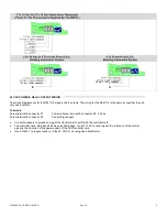
RATIO SETTING
( See also slave application section at the end )
First adjust the vernier stage ratio potentiometer. This will insure a smooth capacity rise of the total load.
Example 1:
The total unit has 100 kW divided in 10 equal stage of 10 kW.
If only 10 kW is used as the modulating stage, then the heater would have 9 on/off mechanical stage plus
one modulating stage. This modulating stage has the same value as all the other stage.
Adjust the vernier stage ratio
potentiometer to 100%.
Example 2:
The total unit still has 100 kW divided in 10 equal stage of 10 kW.
If 20 kW are used as the modulating stage, then the heater would have 8 on/off mechanical stage plus one
modulating stage. The modulating stage has twice the value as all the other stage.
Adjust the vernier stage ratio
potentiometer to 200%.
•
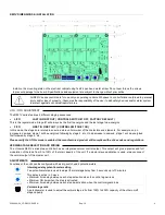
TYPE OF VERNIER STAGE SETTING
The vernier stage output can be configured to operate either as a:
•
Vdc pulsed output to activate an R810 power module
•
0 to 10 Vdc analog output to activate an R820 SCR power controller.
•
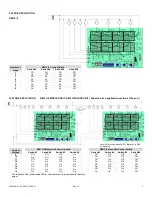
VERNIER STAGE WIRING
Do not wire more than six R810 power module on the
vernier stage output
Respect the polarity between the R851 step controller
board an the R810 power modules
Connect
V
to
+
Connect
COM
to
-
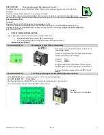
R810
Vdc pulsed to activate R810 power modules
- +
The green status LED on the master unit will cycle at
the same rate as the time proportioning vernier output
For more information, please refer to the R810 service
manual
Set the
R820 SCR
power controller to accept a 0 to 10 Vdc control signal input
Switch
#1, #2 & #3 O
ff
Switch
#4 On
The intensity of the green status LED on the master unit is proportional to vernier output
For more information, please refer to the R820 service manual
R820
SCR Power Controller
ON
ON
1 2 3
I NPUT CONT ROL
1 2 3 4 1 2 3 4 5 6
1 2 3
150
VR2
100
200
RATIO(%)
Control Switch #2 Off
Control Switch #2 On
S
V
COM
0 to 10 Vdc analog output to activate R820 SCR power controller


