

028-5009-04_LIT-R851V-E06-EN
Sep-19
2
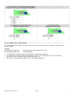
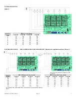
24 VAC POWER & RELAY OUTPUT WIRING
The wiring diagrams are for the R851V-8 models with 8 outputs. The wiring for the R851V-4 is the same except that the unit
only has 4 outputs.
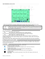
Terminals
Screw terminal & connector #1
Common Screw terminal & connector #2 24 Vac
Screw terminal & connector #3
Control Signal input
•
It is not necessary to ground any leg of the transformer to earth with the controller card.
•
The controller uses internally a half wave rectifier bridge. On 0 to 10 Vdc control signal, the reference of the control
signal is the Common of the power supply of the SCR controller card.
•
Use a Class 1 ( properly fused ) or Class 2, CSA or UL recognized transformer.
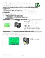
20 mA = 100% capacity
ON
1 2 3
10 Vdc = 100% capacity
ON
1 2 3 4
4
1
1
2
3
I N P U T
1
1
2
3
I N P U T


