Vicon Roughneck Pro V2360W-12 Скачать руководство пользователя страница 18

V2360W Panoramic Fisheye | Quick Guide 


17  -   


3.4 

IP Toolbox 

IP Toolbox is a utility program that helps users to locate the camera(s) in local area network that computer is 

connected to. Note that IP Toolbox works only in Microsoft Windows XP, Microsoft Windows Vista, and 

Microsoft Windows 7 or above. Steps to get the utility program running are listed below.   

1.  Download the IP Toolbox folder to local computer. 

The latest IP Toolbox can be found on Vicon’s website 

Camera Software Download page, vicon-security.com. 

2.  Double click on 

IPToolbox.exe

 in the IP Toolbox

’s folder, and the IP Toolbox window should pop up as 

below. 


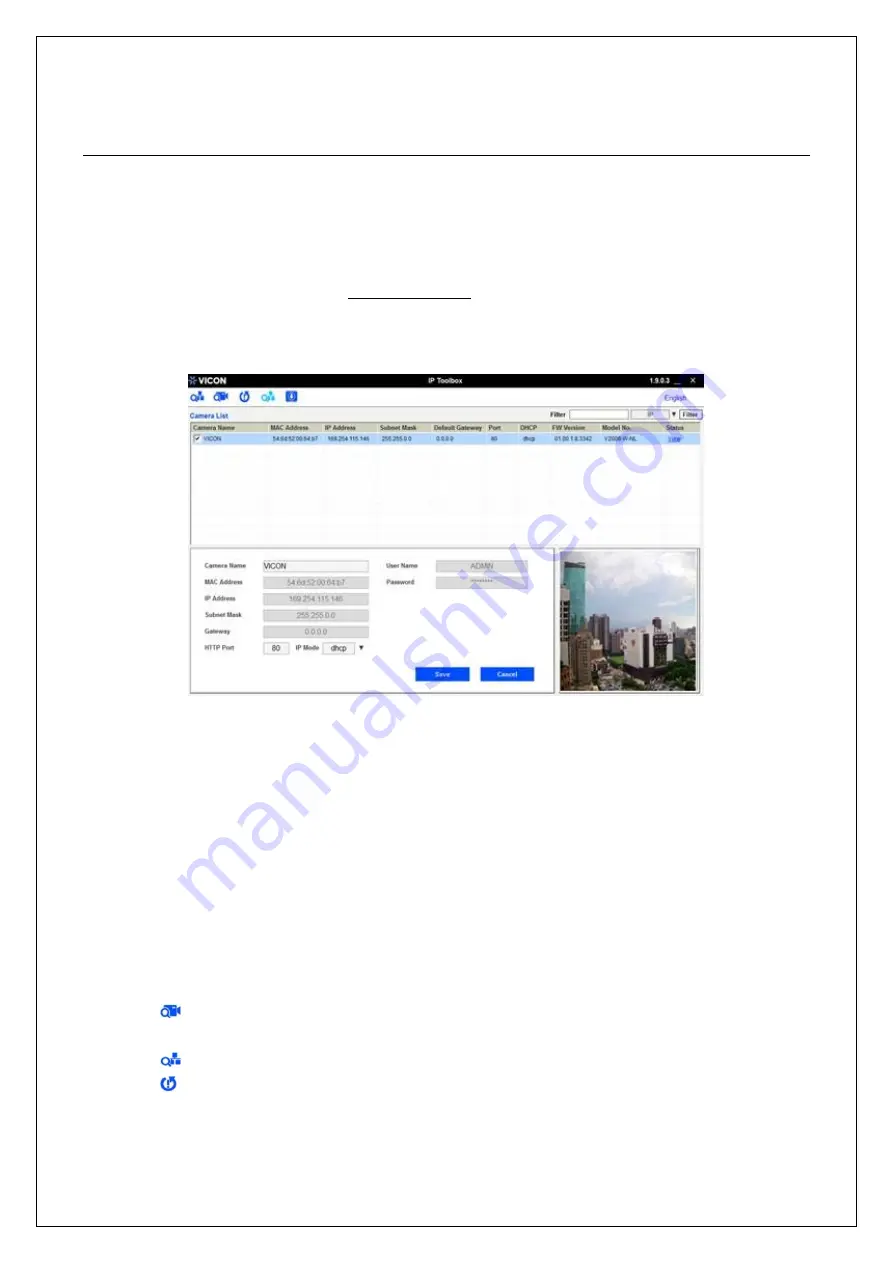
Figure 3 - 7: IP Toolbox 

3.  The window lists information of camera(s) in operation at the present time. Click the camera in the list for 

which you want to configure the network settings. 

4.  Configure the following settings as needed: 


User Name & Password:

 Before performing any operation to any listed camera, enter user name and 

password for the selected camera, and t

hen click “

Verify

” for authentication purposes. 


Camera Name:

 Enter a descriptive name for the camera. 


Network Settings:

 If you have a DHCP server on your network to assign IP addresses to network 

devices, enable the 

“dhcp” option from dropdown menu of 

IP MODE

. Otherwis

e, select “manual” to 

manually enter the values for 

IP Address

Subnet Mask

Gateway

 and 

HTTP Port 

fields. 


Click 

“Save” 

to enable the settings

. Click “

Cancel

” to discard the settings. 

5.  Press 


“View”

 button; the designated browser page of the selected camera will pop up. Input the 

corresponding 

User Name

 & 

Password

 to log in to the specific page of camera. 

6.  Press


“Refresh”

 button; all the cameras currently connected to the network will appear on the list. 

7.  Press


“Initialize”

 button; there are three options, Software default, Hardware default, and Reboot 

camera, for user to perform the factory default or reboot the camera. After clicking the preferred item, a 

warning message will appear. Confirm again before you perform the selected function. 

8.  Th

e “

Filter

” button on the upper-right corner allows user to perform filtering search, which means you can 

Содержание Roughneck Pro V2360W-12

Страница 1: ...warrant that the functions contained in this equipment will meet your requirements or that the operation will be entirely error free or perform precisely as described in the documentation This system...

Страница 2: ...allation and Connection 8 2 1 Package Contents 8 2 2 Installation 8 2 2 1 Checking Appearance 8 2 2 2 Mounting Camera 9 3 Connection 12 3 1 Network Topology 12 3 2 System Requirements 12 3 3 Connectin...

Страница 3: ...operating or storing the camera in the following locations Extremely humid dusty or hot cold environments recommended operating temperature 40 F to 122 F 40 C to 50 C Close to sources of powerful rad...

Страница 4: ...to try to correct the interference by one or more of the following measures Reorient or relocate the receiving antenna Increase the separation between the unit and receiver Connect the unit to an outl...

Страница 5: ...V2360W Panoramic Fisheye Series Quick Guide 4 1 Product Overview 1 1 Physical Characteristics Figure 1 1 Physical Dimension 2 8 70 150 5 5 150 56 99 2 2 Unit mm in...

Страница 6: ...read 1 4 20 the hole is for attaching an additional bracket sold separately for installation flexibility 8 Security Lock The proprietary security lock design ensures camera is mounted securely onto th...

Страница 7: ...evice into the PoE port for network connection and PoE Power over Ethernet capability 24 VAC 12 VDC Power Ports To power on camera connect 12 VDC or 24 VAC power source to the corresponding 2 pin port...

Страница 8: ...supply terminal adaptor for IO connectors and field wiring should comply with the Class 2 Circuit standard for ensuring safety from electrical fires and providing acceptable protection against electri...

Страница 9: ...Guide 1 Guide Pattern 1 2 2 Installation The following tools might help you complete the process of installation Drill Screwdrivers Wire Cutters 2 2 1 Checking Appearance When unpacking check to see i...

Страница 10: ...hreads as needed 24 VAC 12 VDC power cord to the 2 pin power terminal Ethernet cable to the PoE port and the additional audio and alarm input output cables to the 8 pin terminal block Remove the rubbe...

Страница 11: ...ure 2 1 Mounting The Camera Note The correct size holes for TP4 screws with plastic anchors are of diameter 6 35 mm 0 25 in Seal up waterproof rubber hole with plug when no cable is in use Rubber Plug...

Страница 12: ...event the camera from accidentally falling connect the included safety wire with one end on the mounted bracket and the other end to the safety wire screw on the camera Referring to the figure below f...

Страница 13: ...PU 2 40GHZ RAM 6 GB or above Display NVIDIA GeForce 6 Series or ATI Mobility Radeon 9500 System Software Operating System Windows 7 SP1 Windows 8 Windows 10 Browser Internet Explorer 10 11 Mozilla Fir...

Страница 14: ...2 Check whether the network available between the camera and the computer by executing ping the default IP address To do this simply start a command prompt Windows from the Start Menu select Program T...

Страница 15: ...All Cookies Click OK 2 When a proxy server is used click Internet Options on the Tools menus of Internet Explorer select Connect tab click LAN button and set proxy server 3 Change Security in Interne...

Страница 16: ...ns and set as follows Download signed ActiveX controls Prompt recommended Download unsigned ActiveX controls Prompt Initialize and script ActiveX not marked as safe for scripting Prompt Figure 3 4 Sec...

Страница 17: ...tiveX controls marked safe for scripting Enable Figure 3 6 Security Settings 4 4 Press OK to save the settings Close all browser windows and restart the browser This will allow the new settings to tak...

Страница 18: ...and password for the selected camera and then click Verify for authentication purposes Camera Name Enter a descriptive name for the camera Network Settings If you have a DHCP server on your network to...

Страница 19: ...nd connected to predefined network internet controller User Name Password Enter username and password for the current auto set IP address setting Network Interface Controller Select desired network in...

Страница 20: ...button to select a camera or all the cameras on the firmware upgrade list respectively Click Add or Cancel button to confirm the selected cameras for upgrade or to cancel the selection respectively E...

Страница 21: ......

Отзывы: