


13
GT ULTRA ZERO AIR GENERATOR
USER MANUAL
www.vicidbs.com
Version 1.03.0000
6.1.1. Items Not Included in Standard Shipping
NOTE
: The inlet air filter assembly supplied with the unit can also be used to de-pressurize the system by
pressing the pin-valve in the base of the filter housing.
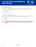
• Additional Filtration
may be required depending on the quality of the air supply. The pre-filter of the
generator will remove nominal amounts of moisture and particulates. If the air supply has excessive
moisture, oil or particulates, then additional filters should be installed.
•
1/4” fitting
to install into the supplied pre-filter. The exact type will depend on the supply tubing or
hose from the air source. A hose clamp is recommended if flexible tubing is used.
•
1/8” fitting
to install into the bulkhead fitting at the output of the unit. The exact type will depend on
the transport tubing or hose of the GC-detection system or analyzer. A hose clamp is recommended if
flexible tubing is used.
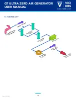
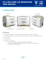
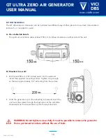
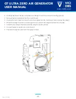
6.2. UNPACK UNIT AND OPEN COVER
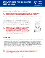
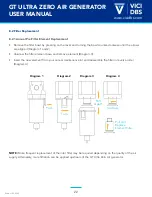
6.3. INSTALL 1/4” EXTERNAL INLET FILTER
• Remove plastic 1/4” inlet & 1/8” outlet port plugs.
•
Apply Teflon pipe sealant tape to both sides of the supplied 1/4” male to male adapter.
•
Thread adapter to output side of the air filter assembly. Do not over tighten.
•
Attach air filter assembly to input side (left side) of the generator, and secure.
CAUTION: Remove plastic protective cover from outside AND inside unit before
plugging in and powering up the unit.
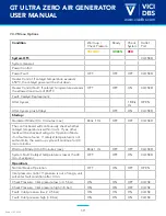
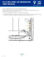
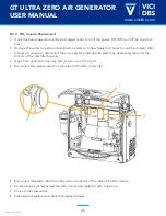
6.4 Check Voltage Setting
Check the setting of the voltage selector on the side of the unit. The set voltage is indicated in the little
window on the inlet power filter.
To change the voltage setting, proceed as follows:
• Using a small screwdriver, remove the voltage selector insert.
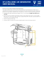
• Replace fuses:
VOLTAGE SETTING
FUSE
240 VAC
4 AT
120 VAC
6 AT
• Replace the voltage selector insert so that the white arrow points to the correct voltage.