Chapter 4 Chassis Web User Interface (UI)
Web UI Pages
Rev. D0
mA-1302/mA-1305 AXIe Chassis Operation Manual
May 2020
Page 4-11
Triggers Page
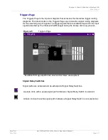
The Triggers Page is the top-level diagram that accesses the interactive trigger routing
diagrams. The black blocks on the Triggers Page open interactive signal routing diagrams
for the selected group of signals. The trigger signals that are available depend on the input
signals detected by the Chassis Shelf Manager during the bootup discovery process.
Signal Relay Switches
Signal paths are activated and de-activated at Signal Relay Switches.
A purple circle with a purple signal path indicates a Signal Relay Switch is selected.
A black circle with a white signal path indicates a Signal Relay Switch is not selected.ac
Figure 4-5
Triggers Page
* MultiShelf I/O signal paths are reserved for future development.
Содержание mA-1302
Страница 1: ...mA 1302 mA 1305 AXIe Chassis Operation Manual ...
Страница 3: ......


