Chapter 2 mA-1302/mA-1305 Controls and Connectors
Rear Panel Controls and Connectors
mA-1302/mA-1305 AXIe Chassis Operation Manual
Rev. D0
Page 2-6
April 2020
Ethernet Connector (5)
The Ethernet Connector is used for basic network connectivity and other functions such as
Wake-on-LAN, Wake-on-Frame and timing synchronization. The Ethernet Connection is
sufficient to perform low speed data transfers and system communication functions
between the Chassis and Host Controller.
The Chassis' Ethernet signal is routed using the Chassis Software Interface.
USB Connector (6)
The USB Connectors are 3.0, Type A connectors which can be used to perform high speed
data transfers to and from the Chassis System Module.
MultiShelf I/O Connector (7)
Reserved for Future Implementation.
Frequency Reference I/O Connector (8)
The Frequency Reference Input Connector is used to connect the Chassis to an external
frequency reference. The Frequency Reference Output Connector allows the Chassis to
be used as a frequency reference by another device. The Chassis Frequency Reference
Input/Output signals are routed and configured using the Chassis Web Browser User
Interface (
“Configure Clock References” on page 5-21
).
Refer to the AXIe Chassis Data Sheet for supported external frequency specifications.
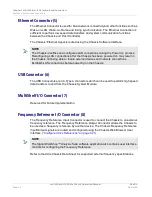
NOTE
The Chassis identifies and configures LAN connections during the Power Up process.
Reconfiguring LAN connections after the Chassis has been powered on may result in
the Chassis not being able to locate external devices and network connections.
Establish LAN connections before powering on the Chassis.
NOTE
The Signal WorkShop™ Analysis Suite software application also contains user interface
controls for configuring the Frequency Reference.
Содержание mA-1302
Страница 1: ...mA 1302 mA 1305 AXIe Chassis Operation Manual ...
Страница 3: ......


