VIPRO VP7910 User Manual
VIPRO VP7910 User Manual
VIPRO VP7910 User Manual
VIPRO VP7910 User Manual
30
3.
3.
3.
3.
Hardware Installation
Hardware Installation
Hardware Installation
Hardware Installation
This chapter provides you with information about hardware installation
procedures.
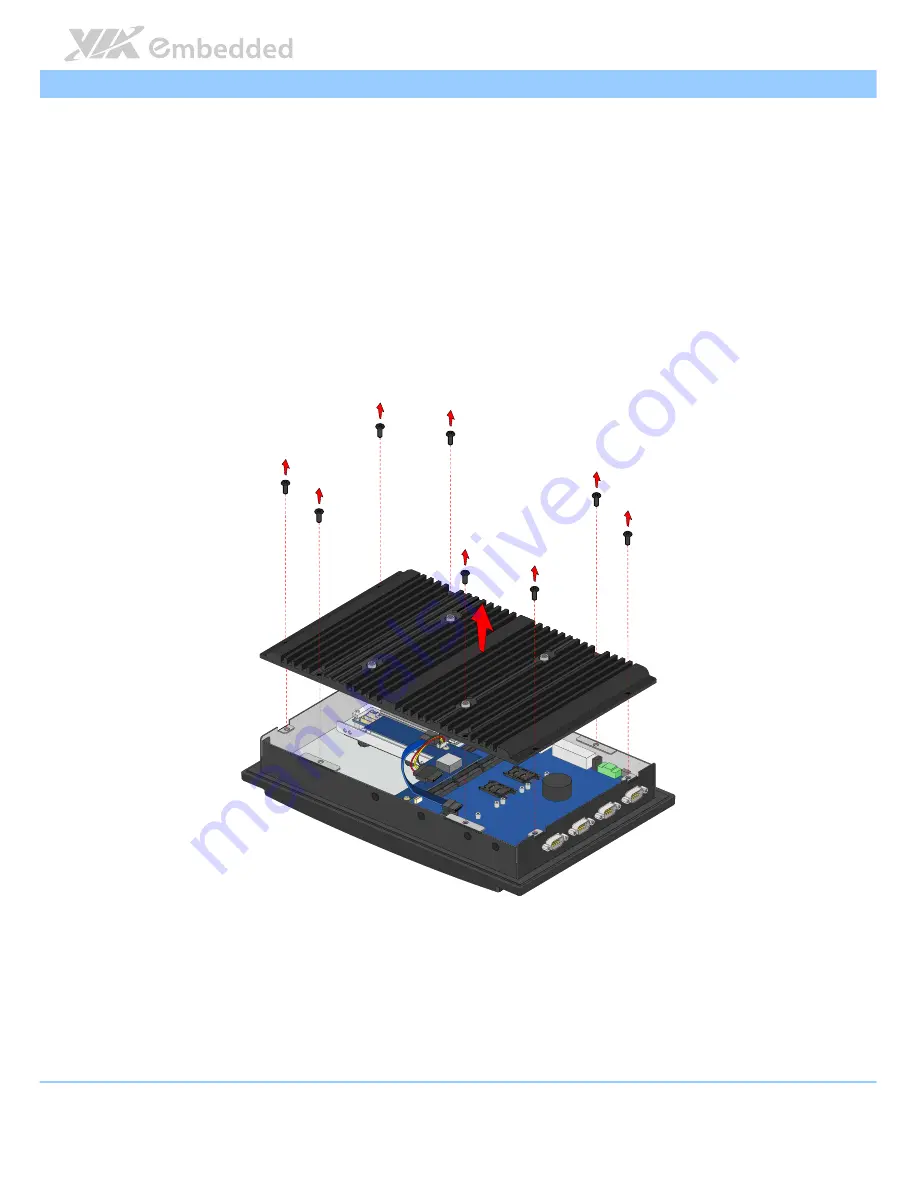
3.1.
How to remove the rear cover plate
Ste
Ste
Ste
Step 1
p 1
p 1
p 1
Remove the eight screws on the top of the rear cover plate.
Figure
Figure
Figure
Figure 21
21
21
21: Removing the rear cover plate
: Removing the rear cover plate
: Removing the rear cover plate
: Removing the rear cover plate
Step 2
Step 2
Step 2
Step 2
Carefully lift up the cover plate.