background image


VIPRO VP7910 User Manual

VIPRO VP7910 User Manual

VIPRO VP7910 User Manual

VIPRO VP7910 User Manual    


23


2.1.5.


USB 2.0 Ports 

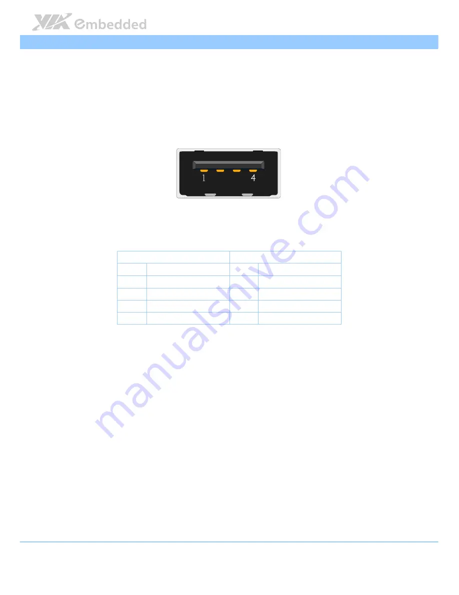
The VIPRO VP7910 has two external USB ports (USB1 and USB2) on the front 

panel. Each USB port gives complete Plug and Play and hot swap capability 

for external devices. The USB interface complies with USB UHCI, Rev. 2.0. 


Figure 

Figure 

Figure 

Figure 14

14

14

14: USB 2.0 port diagram

: USB 2.0 port diagram

: USB 2.0 port diagram

: USB 2.0 port diagram    


USB2

USB2

USB2

USB2    

USB1

USB1

USB1

USB1    

Pin

Pin

Pin

Pin    

Signal

Signal

Signal

Signal    

Pin

Pin

Pin

Pin    

Signal

Signal

Signal

Signal    

VCC 

VCC 

USB data - 

USB data - 

USB data + 

USB data + 

GND 

GND 

Table 

Table 

Table 

Table 3

3

3

3: USB 2.0 port pinout

: USB 2.0 port pinout

: USB 2.0 port pinout

: USB 2.0 port pinout    

Содержание VIPRO VP7910

Страница 1: ......

Страница 2: ...10082015 111900 USER MANUAL VIPRO VP7910 Fanless quad core panel PC with 10 4 resistive or projective capacitive touch screen...

Страница 3: ...ucts described in this manual at any time without prior notice Regulatory Compliance FCC FCC FCC FCC A Radio Frequency Interference Statement A Radio Frequency Interference Statement A Radio Frequency...

Страница 4: ...ce the power cord in such a way that people cannot step on it Always unplug the power cord before inserting any add on card or module If any of the following situations arises get the equipment checke...

Страница 5: ...based fanless 10 4 Resistive touch panel system with 800 x 600 LCD VP VP VP VP 7910 7910 7910 7910 P1Q12A1 P1Q12A1 P1Q12A1 P1Q12A1 1 2GHz VIA Eden X4 CPU based fanless 10 4 Projective Capacitive touc...

Страница 6: ...nd Functionality 21 2 1 1 Power Button 21 2 1 2 DC In Power Input Connector 21 2 1 3 LED Indicators 22 2 1 4 Audio Jacks 22 2 1 5 USB 2 0 Ports 23 2 1 6 GigaLAN Ports LAN1 and LAN2 24 2 1 7 USB 3 0 Po...

Страница 7: ...49 4 5 2 S5 RTC Wake Settings 50 4 5 3 CPU Configuration 51 4 5 4 SATA Configuration 52 4 5 5 F81801 H W Monitor 53 4 5 6 F81865 Super IO Configuration 54 4 5 7 F81865 H W Monitor 57 4 5 8 Clock Gene...

Страница 8: ...O VP7910 User Manual vii 4 8 5 Save Options 72 4 8 6 Save Changes 72 4 8 7 Discard Changes 72 4 8 8 Restore Defaults 72 5 5 5 5 Driver Installation Driver Installation Driver Installation Driver Insta...

Страница 9: ...agram 22 Figure 14 USB 2 0 port diagram 23 Figure 15 Gigabit Ethernet port diagram 24 Figure 16 USB 3 0 port diagram 25 Figure 17 HDMI port diagram 26 Figure 18 VGA connector diagram 27 Figure 19 COM...

Страница 10: ...ngs screen 49 Figure 45 Illustration of the S5 RTC Wake Settings screen 50 Figure 46 Illustration of CPU Configuration screen 51 Figure 47 Illustration of SATA Configuration screen 52 Figure 48 Illust...

Страница 11: ...les Table 1 Power input connector pinout 21 Table 2 Audio jack receptacle description 22 Table 3 USB 2 0 port pinout 23 Table 4 Gigabit Ethernet port pinout 24 Table 5 USB 3 0 port pinout 25 Table 6 H...

Страница 12: ...R3 1333 SODIMM socket that supports up to 2 GB of memory two Gigabit Ethernet port two USB 2 0 ports two USB 3 0 ports three configurable COM connectors with 5V 12V selector and one GPIO connector The...

Страница 13: ...timedia Capabilities ilities ilities ilities Built in 3D 2D performance graphics engine with MPEG 2 VC 1 and H 264 decoding accelerator Dual SIM Stand Dual SIM Stand Dual SIM Stand Dual SIM Stand by c...

Страница 14: ...Panel Wall VESA Mountable Panel Wall VESA Mountable Multiple mounting options make it easy to install anywhere including Panel VESA and Wall mount Embedded OS ready Embedded OS ready Embedded OS ready...

Страница 15: ...Monitoring System Monitoring ACPI Supported Wake on LAN Keyboard power on Timer power on System power management AC power failure recovery Watchdog timer System Memory System Memory System Memory Syst...

Страница 16: ...Type Type Type Type 5 wire analog resistive Light Transmission Light Transmission Light Transmission Light Transmission 80 3 Controller Controller Controller Controller USB interface Driver Driver Dri...

Страница 17: ...1 COM2 and COM3 connector 5V 12V power selection by BIOS setup for COM1 COM3 connector GPIO GPIO GPIO GPIO General Purpose I O General Purpose I O General Purpose I O General Purpose I O Support one G...

Страница 18: ...s 1 x Mini HDMI port 1 x VGA port 2 x Gigabit Ethernet ports 3 x 3 5 audio jacks consisting Line Out Line In and Mic In 1 x Power On Off Button 1 x Green LED indicator Power On Off status 1 x Red LED...

Страница 19: ...ht Weight Weight 3 6 Kg 7 9 lbs Environmental Specification Environmental Specification Environmental Specification Environmental Specification Operating Temperature Operating Temperature Operating Te...

Страница 20: ...l 9 EMC Approved EMC Approved EMC Approved EMC Approved CE FCC Software Compatibility Software Compatibility Software Compatibility Software Compatibility Operating System Operating System Operating S...

Страница 21: ...on LAN Keyboard power on Timer power on System power management AC power failure recovery Watchdog timer System Memory System Memory System Memory System Memory Technology Technology Technology Techn...

Страница 22: ...nsmission Light Transmission Light Transmission Light Transmission 85 Controller Controller Controller Controller USB interface Driver Driver Driver Driver Windows7 Linux Ethernet Ethernet Ethernet Et...

Страница 23: ...onnector GPIO GPIO GPIO GPIO General Purpose I O General Purpose I O General Purpose I O General Purpose I O Support one GPIO connector 8 bit GPIO 5V power source 4GPI 4GPO Mini PCIe Socket Mini PCIe...

Страница 24: ...ing Line Out Line In and Mic In 1 x Power On Off Button 1 x Green LED indicator Power On Off status 1 x Red LED indicator HDD activities status 1 x DC In jack power input 2 pole Phoenix connector Left...

Страница 25: ...vironmental Specification Environmental Specification Environmental Specification Operating Temperature Operating Temperature Operating Temperature Operating Temperature 10 C 50 C with qualified indus...

Страница 26: ...Notes Notes 1 Specifications are subject to change without prior notice 2 As the operating temperature provided in the specifications is a result of the test performed in VIA s chamber a number of var...

Страница 27: ...er Manual VIPRO VP7910 User Manual 16 1 3 Layout Diagram Figure Figure Figure Figure 1 1 1 1 Front side layout Front side layout Front side layout Front side layout Figure Figure Figure Figure 2 2 2 2...

Страница 28: ...910 User Manual VIPRO VP7910 User Manual 17 Figure Figure Figure Figure 3 3 3 3 Rear side layout Rear side layout Rear side layout Rear side layout Figure Figure Figure Figure 4 4 4 4 Bottom side layo...

Страница 29: ...oduct Dimensions Figure Figure Figure Figure 5 5 5 5 Front side view dimensions Front side view dimensions Front side view dimensions Front side view dimensions Figure Figure Figure Figure 6 6 6 6 Bot...

Страница 30: ...r Manual 19 Figure Figure Figure Figure 7 7 7 7 Rear side view dimensions Rear side view dimensions Rear side view dimensions Rear side view dimensions Figure Figure Figure Figure 8 8 8 8 Right side v...

Страница 31: ...r Manual VIPRO VP7910 User Manual VIPRO VP7910 User Manual 20 Figure Figure Figure Figure 9 9 9 9 D D D Dimensions of the mounting bracket imensions of the mounting bracket imensions of the mounting b...

Страница 32: ...n Off Instant Off or 4 second delay and Suspend Figure Figure Figure Figure 10 10 10 10 Power On Off button diagram Power On Off button diagram Power On Off button diagram Power On Off button diagram...

Страница 33: ...e Out Line In and Mic In The Line Out jack is for connecting the external speakers or headphones The Line In jack is for connecting the external audio devices such as CD player tape player etc The Mic...

Страница 34: ...ces The USB interface complies with USB UHCI Rev 2 0 Figure Figure Figure Figure 14 14 14 14 USB 2 0 port diagram USB 2 0 port diagram USB 2 0 port diagram USB 2 0 port diagram USB2 USB2 USB2 USB2 USB...

Страница 35: ...AN1_TD3 7 LAN2_TD3 8 LAN1_TD3 8 LAN2_TD3 Table Table Table Table 4 4 4 4 Gigabit Ethernet port pinout Gigabit Ethernet port pinout Gigabit Ethernet port pinout Gigabit Ethernet port pinout Both LAN1 a...
Страница 36: ...A receptacle connector The pinout of the typical USB 3 0 ports are as shown below Figure Figure Figure Figure 16 16 16 16 USB 3 0 port diagram USB 3 0 port diagram USB 3 0 port diagram USB 3 0 port d...

Страница 37: ...17 17 17 HDMI HDMI HDMI HDMI port diagram port diagram port diagram port diagram Pin Pin Pin Pin Signal Signal Signal Signal Pin Pin Pin Pin Sig Sig Sig Signal nal nal nal 1 TMDS Data2 Shield 2 TMDS...

Страница 38: ...ons up to 2560 x 1536 The pinout of the VGA connector is shown below Figure Figure Figure Figure 18 18 18 18 VGA connector diagram VGA connector diagram VGA connector diagram VGA connector diagram Pin...

Страница 39: ...user needs to set it up into the BIOS Figure Figure Figure Figure 19 19 19 19 COM connector diagram COM connector diagram COM connector diagram COM connector diagram Pin Pin Pin Pin RS RS RS RS 232 Si...

Страница 40: ...IO connector is located on the right side of the chassis The pinout of the DIO connector is shown below Figure Figure Figure Figure 20 20 20 20 DIO connector diagram DIO connector diagram DIO connecto...

Страница 41: ...ides you with information about hardware installation procedures 3 1 How to remove the rear cover plate Ste Ste Ste Step 1 p 1 p 1 p 1 Remove the eight screws on the top of the rear cover plate Figure...

Страница 42: ...moving the SATA cable use the pliers to unplug the cable Figure Figure Figure Figure 22 22 22 22 Unplug the SATA cable Unplug the SATA cable Unplug the SATA cable Unplug the SATA cable Step 2 Step 2 S...

Страница 43: ...e HDD mounting brackets Removing the HDD mounting brackets Removing the HDD mounting brackets Removing the HDD mounting brackets Step 4 Step 4 Step 4 Step 4 Attach the 2 5 SATA hard drive to the hard...

Страница 44: ...e and i Connecting the SATA cable and i Connecting the SATA cable and installing the hard drive nstalling the hard drive nstalling the hard drive nstalling the hard drive Step 6 Step 6 Step 6 Step 6 A...

Страница 45: ...cable Plugging the SATA cable Plugging the SATA cable Step 8 Step 8 Step 8 Step 8 On the bottom side of the rear cover plate remove the hard drive thermal pad protective cover plastic on the hard dri...

Страница 46: ...ng the mSATA flash drive module Inserting the mSATA flash drive module Inserting the mSATA flash drive module Inserting the mSATA flash drive module Step 2 Step 2 Step 2 Step 2 Once the module has bee...

Страница 47: ...3 Step 3 Step 3 Connect the SATA data cable into the I O board and connect the other end of the cable to the SATA port 2 on the system s mainboard Figure Figure Figure Figure 32 32 32 32 Connecting th...

Страница 48: ...e socket and place the SIM card inside the socket Ensure the angled corner of the SIM card is placed in the correct way before closing the socket Figure Figure Figure Figure 33 33 33 33 Installing the...

Страница 49: ...34 34 34 34 Installing the 3G GPS WL Installing the 3G GPS WL Installing the 3G GPS WL Installing the 3G GPS WLAN module AN module AN module AN module Step 2 Step 2 Step 2 Step 2 Once the module has b...

Страница 50: ...S Removing the 3G GPS WLAN antenna hole cover WLAN antenna hole cover WLAN antenna hole cover WLAN antenna hole cover Step 4 Step 4 Step 4 Step 4 Insert the 3G GPS WLAN port connectors into the antenn...

Страница 51: ...VIPRO VP7910 Step 1 Step 1 Step 1 Step 1 Prepare and cutout a designated space on the wall for embedding the VIPRO 7910 A recommended cutout dimension is shown below Figure Figure Figure Figure 38 38...

Страница 52: ...Step 2 Step 2 Step 2 Once the cutout has been prepared slide the VIPRO VP7910 backwards into the panel opening Figure Figure Figure Figure 39 39 39 39 Inserting the VP7910 to the wall cutout Inserting...

Страница 53: ...her side of the panel align the panel mounting bracket on the rear side of the VIPRO VP7910 and attach the four screws through the mounting bracket into the rear cover plate Figure Figure Figure Figur...

Страница 54: ...IPRO VP7910 User Manual 43 Step 4 Step 4 Step 4 Step 4 Secure the mounting bracket to the wall with four screws Figure Figure Figure Figure 41 41 41 41 Securing the mounting brackets Securing the moun...

Страница 55: ...ys Up Up Up Up Move up one row Down Down Down Down Move down one row Left Left Left Left Move to the left in the navigation bar Right Right Right Right Move to the right in the navigation bar Enter En...

Страница 56: ...3 Getting Help The BIOS Setup Utility provides a Gener Gener Gener General Help al Help al Help al Help screen This screen can be accessed at any time by pressing F1 F1 F1 F1 The help screen displays...

Страница 57: ...tion of the Main menu screen Illustration of the Main menu screen Illustration of the Main menu screen Illustration of the Main menu screen 4 4 1 BIOS Information The content in this section of the sc...

Страница 58: ...ar segments The and keys on the number pad can be used to change the values The weekday name is automatically updated when the date is altered The date format is Weekday Month Day Year 4 4 5 System Ti...

Страница 59: ...ng arrowhead Figure Figure Figure Figure 43 43 43 43 Illustration of the Advanced Settings screen Illustration of the Advanced Settings screen Illustration of the Advanced Settings screen Illustration...

Страница 60: ...of the ACPI Settings screen Illustration of the ACPI Settings screen Illustration of the ACPI Settings screen 4 5 1 1 4 5 1 1 4 5 1 1 4 5 1 1 Enable Hibernat Enable Hibernat Enable Hibernat Enable Hib...

Страница 61: ...C S5 RTC Wake Settings screen Wake Settings screen Wake Settings screen Wake Settings screen 4 5 2 1 4 5 2 1 4 5 2 1 4 5 2 1 Wake system with Fixed Time Wake system with Fixed Time Wake system with Fi...

Страница 62: ...tion screen shows detailed information about the built in processor In addition to the processor information the thermal controls can be set Figure Figure Figure Figure 46 46 46 46 Illustration of Ill...

Страница 63: ...ration of SATA Configuration screen Illustration of SATA Configuration screen Illustration of SATA Configuration screen Illustration of SATA Configuration screen 4 5 4 1 4 5 4 1 4 5 4 1 4 5 4 1 SATA M...

Страница 64: ...ows monitor hardware status Figure Figure Figure Figure 48 48 48 48 Illustration of F81801 H Illustration of F81801 H Illustration of F81801 H Illustration of F81801 H W Monitor screen W Monitor scree...

Страница 65: ...ial Port 1 Configuration Serial Port 1 Configuration Serial Port 1 Configuration Set parameters of Serial Port 1 COMB 4 5 6 1 1 4 5 6 1 1 4 5 6 1 1 4 5 6 1 1 Serial Port Serial Port Serial Port Serial...

Страница 66: ...age Selection Select COM Output voltage Disabled 5 RI 12V RI 4 5 6 3 4 5 6 3 4 5 6 3 4 5 6 3 Serial Port 3 Configuration Serial Port 3 Configuration Serial Port 3 Configuration Serial Port 3 Configura...

Страница 67: ...5 6 5 4 5 6 5 4 5 6 5 PCIe Mini Card Configuration PCIe Mini Card Configuration PCIe Mini Card Configuration PCIe Mini Card Configuration PCIe A B Mini Card configuration 4 5 6 5 1 4 5 6 5 1 4 5 6 5...

Страница 68: ...l 57 4 5 7 F81865 H W Monitor The F81865 H W Monitor screen shows monitor hardware status Figure Figure Figure Figure 50 50 50 50 Illustration of F81865 H W Monitor screen Illustration of F81865 H W M...

Страница 69: ...tion screen n of Clock Generator Configuration screen 4 5 8 1 4 5 8 1 4 5 8 1 4 5 8 1 CPU Spread Spectrum CPU Spread Spectrum CPU Spread Spectrum CPU Spread Spectrum The Spread Spectrum Setting featur...

Страница 70: ...5 9 1 4 5 9 1 4 5 9 1 4 5 9 1 OnBoard LAN Enable OnBoard LAN Enable OnBoard LAN Enable OnBoard LAN Enable The OnBoard LAN Enable feature determines whether the onboard LAN controller will be used or n...

Страница 71: ...O VP7910 User Manual VIPRO VP7910 User Manual VIPRO VP7910 User Manual VIPRO VP7910 User Manual 60 4 5 9 4 4 5 9 4 4 5 9 4 4 5 9 4 Level Level Level Level Select Backlight Control level 0 20 40 60 80...

Страница 72: ...n Sub screen links can be identified by the preceding right facing arrowhead Figure Figure Figure Figure 53 53 53 53 Illustration of Chipset Settings screen Illustration of Chipset Settings screen Ill...

Страница 73: ...tion of DRAM Configuration screen 4 6 1 1 4 6 1 1 4 6 1 1 4 6 1 1 DRAM Clock DRAM Clock DRAM Clock DRAM Clock The DRAM Clock option enables the user to determine how the BIOS handles the memory clock...

Страница 74: ...he 633 MHz option forces the BIOS to be fixed at 1266 MHz for DDR3 memory modules 667 MHz 667 MHz 667 MHz 667 MHz The 667 MHz option forces the BIOS to be fixed at 1334 MHz for DDR3 memory modules 4 6...

Страница 75: ...Device Control Select Display Device Control Select Display Device Control Select Display Device Control Available selections are Auto and Manual 4 6 2 2 4 6 2 2 4 6 2 2 4 6 2 2 Select Display Device...

Страница 76: ...d with the system The panel types are predefined in the VGA VBIOS Panel Type Panel Type Panel Type Panel Type Resolution Resolution Resolution Resolution Panel Type Panel Type Panel Type Panel Type Re...

Страница 77: ...6 56 Illustration of PMU_ACPI Configuration screen Illustration of PMU_ACPI Configuration screen Illustration of PMU_ACPI Configuration screen Illustration of PMU_ACPI Configuration screen 4 6 3 1 4 6...

Страница 78: ...f Power Off Power Off The Power Off option keeps the system in an off state until the power button is pressed again Power On Power On Power On Power On The Power On option restarts the system when the...

Страница 79: ...f Others Configuration screen Illustration of Others Configuration screen 4 6 4 1 4 6 4 1 4 6 4 1 4 6 4 1 WATCHDOG Timer Enable WATCHDOG Timer Enable WATCHDOG Timer Enable WATCHDOG Timer Enable When t...

Страница 80: ...ngs screen Illustration of Boot Settings screen Illustration of Boot Settings screen Illustration of Boot Settings screen 4 7 1 Boot Configuration The Boot Settings Configuration screen has several fe...

Страница 81: ...4 7 2 1 4 7 2 1 4 7 2 1 Launch PXE OpROM policy Launch PXE OpROM policy Launch PXE OpROM policy Launch PXE OpROM policy Do not launch Do not launch Do not launch Do not launch Prevent the option for L...

Страница 82: ...lustration of Save Exit screen Illustration of Save Exit screen 4 8 1 Save Changes and Exit Save all changes to the BIOS and exit the BIOS Setup Utility The F10 hotkey can also be used to trigger this...

Страница 83: ...the BIOS Setup Utility was launched The F7 hotkey can also be used to trigger this command 4 8 5 Save Options Save Changes done so far to any of the setup options 4 8 6 Save Changes Save system config...

Страница 84: ...ite at www viatech com en 5 2 Linux Driver Support The VIPRO VP7910 is compatible with many Linux distributions Support and drivers are provided through various methods including Drivers provided by V...

Страница 85: ......

Отзывы: