background image


11

/12


4. Offline controller 

(Optional) 

Note: The offline controller and the computer cannot be connected to the engraving machine at the same time. When 
using the offline controller, please make sure that the USB cable of the machine and the computer is disconnected.
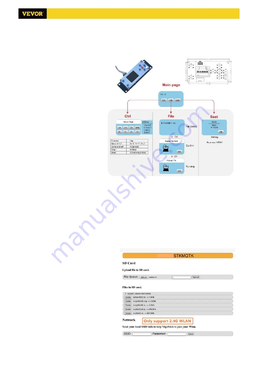


4.1 Main page: 
Y-

: right 

Y+

: left   

Z+

: Send $X to the GRBL 

motherboard to unlock it. 

OK/SPN

: Confirm button. 


4.2 Control page:


Manually move each axis to the desired 
position.   

X+

: X axis move right direction, 

X-

 opposite. 

Y+

: Y axis move forward direction, 

Y-


opposite. 

Z+

: Z axis move up direction, 

Z-


opposite.   

OK/SPN

: Spindle test switch, press to open 

the spindle (corresponding to SPN gray on 
the screen), press again to close the spindle 
(the corresponding SPN on the screen 
returns to normal). Long press to enter 
changing spindle speed page. At this page, 
Y+/Y- is High/Low spindle speed, long press 
OK/SPN to exit the changing spindle speed 
page. 

Exit/STP

: Function 1: Tap on each axis button 

of XYZ to change the movement distance by 
0.1, 1, 5, 10 cycles each time. Function 2: Press and hold for about 2 seconds to exit. 
 

4.3 File page: 

File list Select the file to be engraved. Support documents include: NC, NCC, TAP, TXT, Gcode, GCO, NL, CUT, CNC . 

Y+

: up, 

Y-

: down 

OK/SPN

: Confirm the selection and enter the confirmation engraving page. 


4.4 Confirm the engraving page: 

Confirm that the engraving file is started without errors. 

OK/SPN

: Confirmation starts, ready to print becomes the progress display percentage, the file selection page is 

returned after the engraving is completed. 
 

4.5 Settings page: 
X+

X-

: Chang Baud rate; 

Y+

/

Y-

: Change Feed rate 

by 

±

100/Click; 

Z+

/

Z-

: Change Feed rate by 

±

10/Click; 
 

4.6 WiFi Network 

The offline controller has WiFi wireless network 
function. By default, the WiFi hotspot of 

VIGO-

STK****

 is automatically established. You can 

connect to the hotspot through the WiFi of your 
computer or mobile phone, and then open 

192.168.0.1

 or 

vigostick.local

 in browser to 

manage (upload or delete) the files on the SD card 
of the offline controller, and you can also enter the 
SSID (Only support 2.4G signal) account and 
password to help the offline controller access your 
local WiFi network. After the controller is connected 


Содержание S3018 Prover

Страница 1: ...wn steps first cut off the power then pull out the USB cable Precautions 1 All parts description just for illustrative purpose If there is any difference please refer to the actual part shape 2 Please make sure that the machine is under care when it is working 3 If your machine is equipped with an offline controller please note that the offline controller and the computer cannot be connected to th...

Страница 2: ...ssembled 4 G9 Self tapping screw M2 6 8 Already assembled 2 Part No Part Name Explanation Quantity Picture G10 Self tapping screw M2 6 6 Already assembled 4 9 1 Pressing plate 50 20 3 4 G11 Shim Already assembled 2 9 2 Screw M6 40 4 G12 Z1 Z2 Limit wire 2 0 2 54 Length 600mm 2 9 3 Screw M6 45 4 G13 X Y2 Limit wire 2 54 3P Length 600mm 2 9 4 Butterfly nut M6 4 G14 Y1 Limit wire 2 54 3P Length 300mm...

Страница 3: ...3 12 X axis and Y axis component assembly 1 X axis component 1Set 4 Trapezoidal nut M5 20 8PCS 3 M5 16 8PCS 3018 Prover Ver V1 2 2 Machine Assembly 2 Y axis component 1Set ...

Страница 4: ...4 12 Control board and emergency stop switch assembly C3 Ship nut M5 10 4PCS C1 Control board 1PCS C2 M5 12 4PCS G1 Emergency stop switch 1Set 3018 Prover Ver V1 2 ...

Страница 5: ...5 12 Y limit switch and rubber mat assembly 6 Trapezoidal nut M4 20 4PCS 7 Rubber mat 4PCS 5 M4 10 4PCS G11 Shim 2PCS G3 Y limit switch 2PCS G8 M3 6 4PCS 3018 Prover Ver V1 2 ...

Страница 6: ...6 12 Guard plate assembly D1 Guard plate 2PCS C3 Ship nut M5 10 8PCS D2 M5 10 8PCS 3018 Prover Ver V1 2 ...

Страница 7: ... Y1 Axis X Axis Spindle Motor 24V Power 48V Spindle Motor 0 500W Power 24V DC USB Emergency Stop X Limit Z Axis Y1 Axis Y1 Limit Y2 Limit X Axis Spindle Motor Z1 Limit Z2 Limit 7 12 3018 Prover Ver V1 2 2 0 2 54 Length 600mm 2 0 2 54 Length 600mm 2 54 3P Length 300mm 2 54 3P Length 600mm 2 54 3P Length 600mm 2P Length 480mm 4P Length 480mm 4P Length 150mm 4P Length 480mm ...

Страница 8: ...and blocks all G code commands 3 2 Control Home button Starts the homing cycle procedure with H command Z probe Starts the zero Z axis search procedure using the command specified in the settings Z probe commands box Example command G91G21 G38 2Z 30F100 G0Z1 G38 2Z 1F10 Zero X Y Zeroes the X and Y coordinates in the local coordinate system Also retains an local system offset G92 for later use Rest...

Страница 9: ... rate click Finish The status bar at the top right of the Candle interface will show Idle and at the same time the console at the bottom right will display the information shown below indicating that the connection has been successfully established 4 Processing documents Click File option at the top of candle then click New to create G Code On the command bar at the bottom of the interface click O...

Страница 10: ...reset to zero the are zeroing X Y and Z axes buttons Before returning to zero make sure that the tool approaches the distance of one sheet of paper for engraving and then return the X Y and Z axes to zero please use a flat bottom sharp knife when engraving and use a cylindrical milling cutter when machining planes slots and holes The effect is that the sculpted figure will be carved with the blade...

Страница 11: ... 0 1 1 5 10 cycles each time Function 2 Press and hold for about 2 seconds to exit 4 3 File page File list Select the file to be engraved Support documents include NC NCC TAP TXT Gcode GCO NL CUT CNC Y up Y down OK SPN Confirm the selection and enter the confirmation engraving page 4 4 Confirm the engraving page Confirm that the engraving file is started without errors OK SPN Confirmation starts r...

Страница 12: ...tuck or the stepper motor does not move please try to restore the factory settings of the main board The recovery method is as follows Method 1 Go to our website www VevorEngraver com to download VigoWorks software For Windows and run it Click the button Connect After the software connected the machine successfully click Settings On the settings window Click Restore Factory button then reboot the ...

Отзывы: