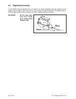
400202.01
33
vetus®
Installation manual VF4 VF5
5
Electric/electronic system
5.1 Electrical system
5.1.1 Battery connection
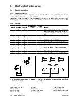
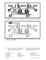
Here below you will find a series of diagrams how to connect the batteries in case that it is necessary to use an
auxiliary battery or in case of a twin engine installation.
The alternator should charge also the auxiliary battery without having the auxiliary battery getting discharged by
transferring power to the engine battery. Use either a battery selector switch or a diode splitter to achieve this.
5.1.2 Diagrams
Diagram Engines Batteries
Battery selec-
tor switches
Diode
splitters
Remarks
1
1
1
Reference diagram, Engine wiring as supplied
2
Ground connections; all ground connections
together must be tied together to one ground
point.
3
1
2
1
4
1
2
1
5
1
2
1
Connection of battery charger
6
1
2
1
1
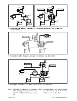
One starter battery, one domestic battery
7
2
2
1
8
2
2
2
9
2
3
2
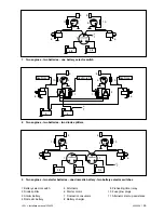
Two starter batteries, one domestic battery
10
2
2
1
2
11
2
2
1
2
Connection of battery charger
12
2
3
2
Two starter batteries, one domestic battery
1 Battery selector switch
2 Diode splitter
3 Starter battery
4 Domestic battery
5 Alternator
6 Starter motor
7 Domestic consumers
8 Battery charger
9 Preheating timer relay
10 Fuse glow plugs
11 Alternator start-up assistance
3
5
6
9
10
1 As a reference a diagram of the engine
wiring as supplied
3
3
3
3
3
3
2 Use one ground point to tie all ground connections
together.
Содержание VF4.140E
Страница 1: ...Installation manual VF4 VF5 VF4 140E VF4 170E VF4 190E VF5 220E VF5 250E ...
Страница 2: ...vetus Installation manual VF4 VF5 400202 01 Copyright 2012 Vetus n v Schiedam Holland ...
Страница 22: ...20 400202 01 vetus Installation manual VF4 VF5 ...
Страница 68: ...66 400202 01 vetus Installation manual VF4 VF5 ...
Страница 71: ...400202 01 69 vetus Installation manual VF4 VF5 ...
Страница 72: ...340401 01 12 07 Nederlands Printed in the Netherlands Vetus Diesel VF4 VF5 Nederlands ...


