2
Tamper Switch
The tamper switch is designed to protect against unauthorized cover opening. When the tamper is triggered, Door
Contact will emit a signal to the Control Panel for reporting, the LED will also light up.
Battery
The MDC-3 uses one
3V CR2450 Lithium battery
as its power source. The Door Contact is also capable of detecting
low battery. When the battery is low, a low battery signal will be sent to the Control Panel along with regular transmission.
The LED will light up when the Door Contact is activated under low battery status.
Changing Battery
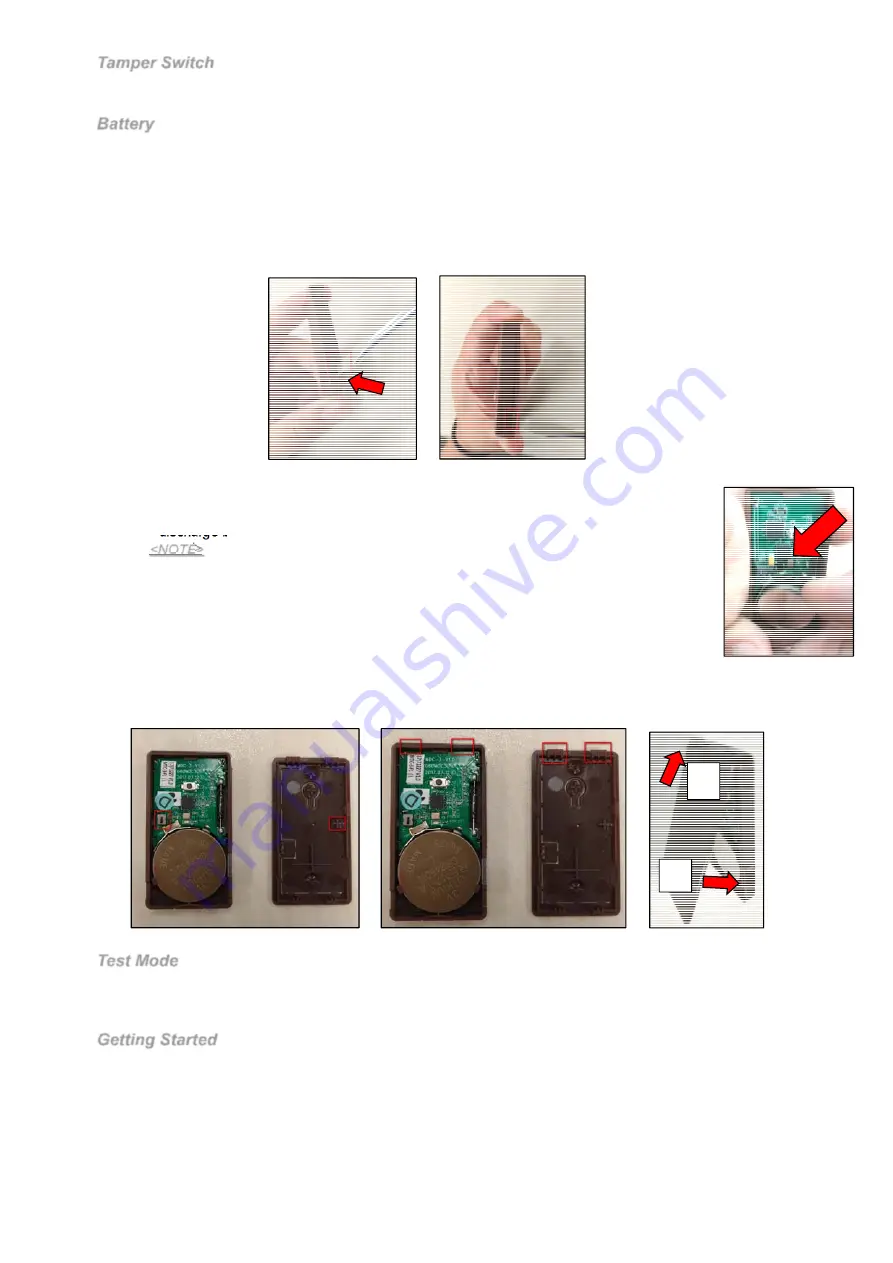
You need to open the cover to insert/remove the battery
Step 1. Use a flat-headed screwdriver to fit into the cover opening hole on one side as (
Pic1
).
Step 2. Push the flat-headed screwdriver upwards as (
Pic2
).
Step 3. Turn to the other side and repeat Step 1 and Step 2.
(Pic 1)
(Pic 2)
Step 4. Once the cover is opened, you can proceed to change the battery.
Step 5. After the battery has been removed, press the Learn / Test button 5-6 times to fully
discharge before inserting the new battery.
<NOTE>
Make sure the battery mark with the positive side (+) is faced upwards when
inserting the battery.
Make sure to insert or place the battery from the top right angle as indicated in the
picture. (
Pic3
)
Step 5. To replace the cover:
- Make sure the Tamper Compression Mark is aimed at the Tamper Switch (
Pic 4
)
(Pic 3)
- Also make sure the bottom hooks of the back cover is latched on the bottom of the front cover (back) as (
Pic 5
)
- Fit the bottom hooks into the bottom latches of the front cover (back) then push it downwards as (1) in (
Pic 6
)
then push forward (2) the entire back cover to close it until you hear a clip sound.
(Pic 4)
(Pic 5)
(Pic 6)
Test Mode
The Door Contact can be put into Test mode for 3 minutes by pressing the Test Button once.
Under Test Mode, the LED will light up whenever the Door Contact is activated.
Each additional Test Button press will reset Test Mode time to 3 minutes.
Getting Started
Step 1: Remove the battery insulator of the Door Contact.
Step 2: Put the Control Panel into learning mode, refer to Control Panel manual for detail.
Step 3: Press the Learn/Test Button on
Door Contact to send signal to the Control Panel.
Step 4: If the Control Panel successfully receives the signal, the Control Panel should respond (e.g. emitting beeps).
Refer to your Control Panel manual to complete the learning process.
Step 5: After the Door Contact is learnt-in, put the Control Panel into “
Walk Test
” mode, hold the Door Contact at the
desired location, and press the Test button to confirm if this location is within signal range of the Control Panel.
Step 6: When you are satisfied with the Door Contact at the chosen location, proceed to
installation
.
1
2


