background image


5.2 Electric Connection 

 
1.  Before connecting the appliance to the network, check the following: 


Network voltage corresponds to the data written in the plate. 


Grounding is efficient. 


The connection cable is suitable to the power absorbed by the appliance. 

2. 

Place  a  device  before  the  appliance  itself  that  allows  the  unit’s  disconnection  from  the  mains 

circuit in an omnipolar way; this device must have an opening of contacts of at least 3mm. safety 

switches can be used. The omnipolar switch must be close to the appliance, be approved and 

have a section suitable to the appliance. 

3.  The  cable  must  be  the  Oil  resistant  type.  The  YELLOW-GREEN  ground  cable  must  be  longer 

than the others in the event that, if the cable stopper breaks, the cable will disconnect after the 

tension  cables. 

The  YELLOW-GREEN  cable  must  never  be  broken. 

The  yellow-green  cable 

must be connected to the terminal firstly and then connected to the outer layer. The grounding 

element must be attached to the machine enclosure. 


5.3 Adjustable Foot And Caster Installation 


When install the adjustable foot, make the mounting screws into correct position and tighten up. 

According to the machine balance , could adjust the screw on the feet to make stable. 


Caster installation


1.  The  casters  with  the  brakes  are  installed  in  the  front,  and  the  casters  without  the  brakes  are 

installed in the rear. 

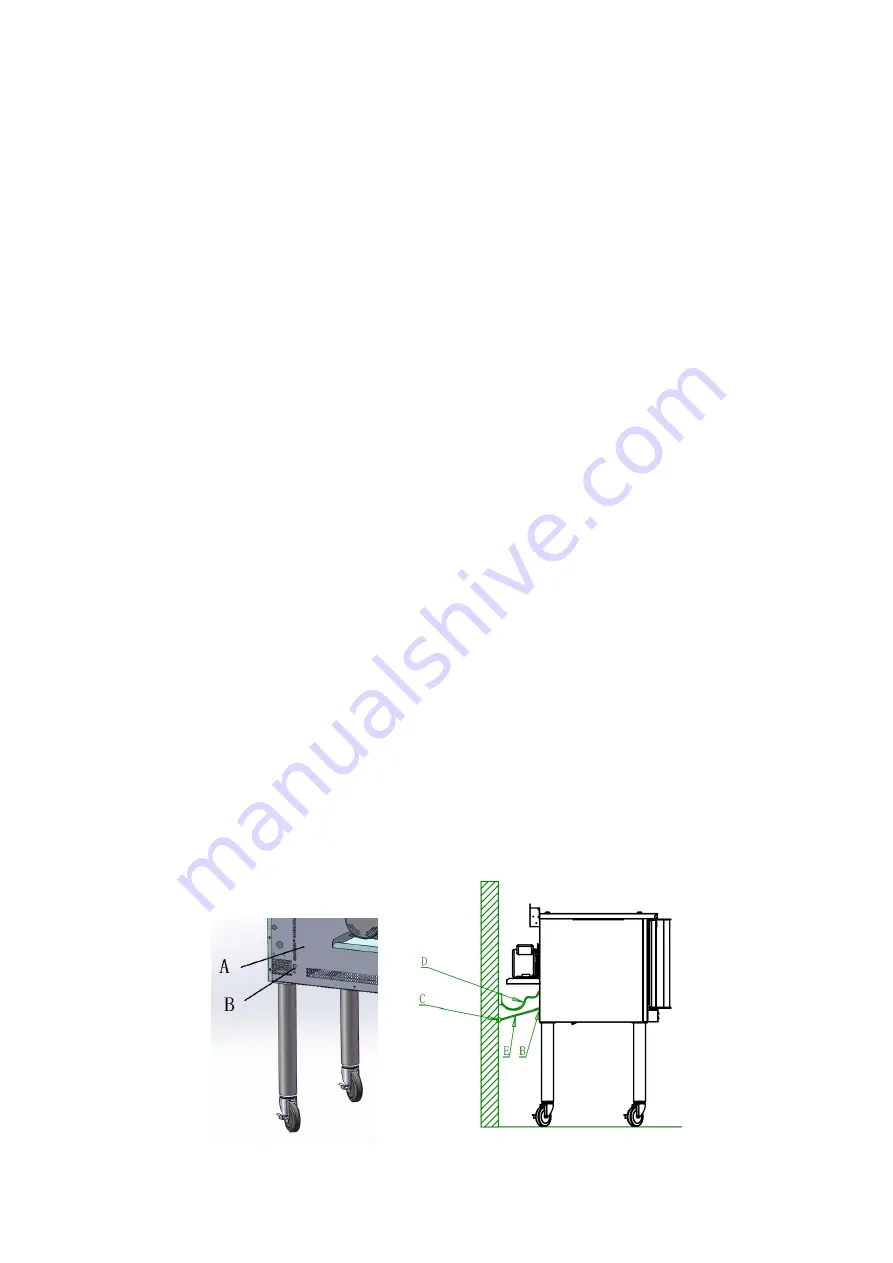
2.  The electric convection oven equipped with caster must be installed the limit devices at the same 

time. To limit the pulling power cord or connector (below D), this device can soft connect oven 

back and the wall or floor.   

3.  The chain or wire rope are available to use for connection material(below E). One end is fixed on 

the wall or the ground (below C), another end is fixed at the back of the oven (back strip gaps, the 

following  figure  location  B);  The  fixed  length  is  no  more  than  4/5  of  the  power  cord(figure  D). 

Vesta does not provide the required connection materials and joints. 


Fig.2


Содержание FEC100

Страница 1: ...FEC100 Electric Convection Oven User s Manual ...

Страница 2: ...y before carry out any action on this device especially when starting The manufacturer declines any responsibility in the event users do not follow the instructions or guidelines stated here The user s manual should be placed close to the device in convenience of users reading before operation We have the full authority to reserve the further technical changes of the device in the scope of further...

Страница 3: ...e of personal safety as well as proper instructions guidance those who were mentioned above can make some particular operation of this device Keep children away from the device Preserve this manual safely When passing on selling the device to a third party the manuals must be handed over along with the device All users must operate the device complying with the user s manual and related safety gui...

Страница 4: ...al Introduction 1 2 Specifications 1 3 Structure Schematic Diagram 2 4 Basic Features Parameters 3 5 Precautions Recommendations 3 6 Working Instructions Operation Flow 7 7 Electrical Diagram 10 8 Cleaning Maintenance 11 ...

Страница 5: ...ction oven single or double layer free combination monolayer two layer for free combination Standard specification 10 5Kw layer two speed fan with cooling function driven by the efficient 1 2 1 10HP air cooling fan motor The door interlocking switch have the function to turn off the motor heating tubes automatically when the door opened In the air cooling code the fan is started when the door is o...

Страница 6: ...2 3 Structure Schematic Diagram Stainless Steel Feet Version Caster Version Double Stacked Version ...

Страница 7: ...33 1710 1120 FEC100 10 1 11 9 220 240 3 30 27 30 1425 933 1710 1120 FEC100 9 0 208 1 43 43 1425 933 1710 1120 FEC100 10 1 11 9 220 240 1 50 50 1425 933 1710 1120 FEC100D 9 0 208 3 27 24 27 1425 933 1710 1120 FEC100D 10 1 11 9 220 240 3 30 27 30 1425 933 1710 1120 FEC100D 9 0 208 1 43 43 1425 933 1710 1120 FEC100D 10 1 11 9 220 240 1 50 50 1425 933 1710 1120 FEC100D L 11 5 208 3 34 31 34 1425 933 1...

Страница 8: ... Do not mount above other cooking equipment 5 Law provisions technical regulations and directives The manufacturer declares that the appliances comply with the EEC directives and the particular reference regulations The manufacturer requires the installation to be performed according to the regulations in force Before installing check that the following provisions are met Building regulations and ...

Страница 9: ...o the terminal firstly and then connected to the outer layer The grounding element must be attached to the machine enclosure 5 3 Adjustable Foot And Caster Installation When install the adjustable foot make the mounting screws into correct position and tighten up According to the machine balance could adjust the screw on the feet to make stable Caster installation 1 The casters with the brakes are...

Страница 10: ...r to use 2 During stacking replace the long leg with 6 leg or caster as indicated in Fig 3 Fig 3 3 Fix the intersection area between the top and bottom appliance with a connecting panel as indicated in Fig 4 Fig 4 A Oven Back B Limiting Position the another end is fixed to the wall or ground C Fixed on the wall D Power cord E Chain Install the connecting panel ...

Страница 11: ... will disappear after two or three uses 5 After use the areas are hot for a certain amount of time residual heat Avoid resting your hands on them and allowing children to get too close 6 These are very important regulations if they are neglected the appliance may not perform properly or the user may be placed at risk 7 The appliance is strictly for professional use and must be used by qualified pe...

Страница 12: ...do not use Cook Timer Turn knob to set a time duration An alarm will sound when the timer runs out Turn the knob to OFF to cancel the alarm The timer is a reminder to the user the timer does not control the oven HEAT ON Indicator The HEAT ON indicator will light when the burners are on and will remain on while the oven preheats Power light Switch ON and the light on Switch OFF and the light off Co...

Страница 13: ...ad from the oven If so desired turn the Cook Timer knob until the indicator mark points to the desired cooking time up to 60 minutes The timer knob will rotate counterclockwise as the timer runs down indicating how much time remains You can turn the knob while cooking to increase or decrease the remaining time When the timer runs out a buzzer will sound To immediately silence the buzzer turn the C...

Страница 14: ... contactor HL1 interior light EH1 EH2 EH3 electric heating tubes HL2 HL3 indicator light QF air switch M motor S1 protection switch of Electrical box PT timer S2 power switch HA buzzer S3 Door control IC electronic thermostat S4 interior light switch θ temperature limiter S5 cooling switch ...

Страница 15: ...nd they can be removed with a detergent diluted in water and a Scotch Brite sponge If dirt is tough do not use sandpaper or rough paper but use synthetic sponges for example Scotchbrite sponges 5 Do not use substances for cleaning silver and be careful with hydrochloric or sulphuric vapors coming from floor washing products for example Do not aim water jets directly on the appliance it might be da...

Отзывы: