


18
20303735
VWDV70 Series Gas Fireplace
VentInG InstaLLatIon
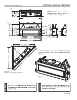
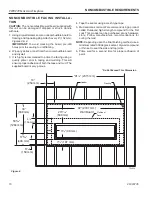
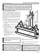
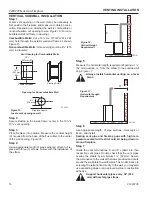
Example:
Elbow 1 = 90°
Elbow 2 = 45°
Elbow 3 = 45°
Elbow 4 = 90°
Total Angular Variation = 270°
Figure 21 -
Maximum Elbow Usage
1
2
3
4
1
2
3
4
FP1180
max bends
36" (914 mm)
Minimum
FP1180
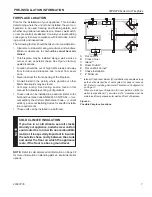
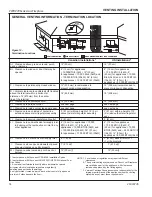
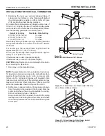
BeLoW GraDe InstaLLatIons
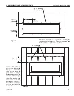
When it is not possible to meet the required vent terminal
clearances of 12" above grade level, a snorkel kit is recom-
mended. It allows installation depth down to 7" (178 mm)
below grade level. The 7" (178 mm) is measured from the
center of the horizontal vent pipe as it penetrates through
the wall.
ensure that sidewall venting clearances are observed.
If venting system is installed below ground, we recom-
mend a window well with adequate and proper drainage
to be installed around the termination area.
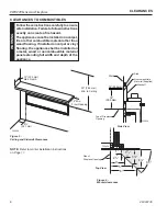
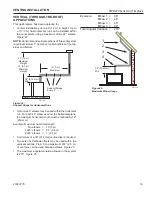
If installing a snorkel, a minimum 36" (914 mm) vertical
rise is necessary. The maximum horizontal run with the 36”
(914 mm) vertical pipe is 36". This measurement is taken
from the collar of the fireplace (or transition elbow) to the
face of the exterior wall. See the Sidewall Venting Graph
for extended horizontal run if the vertical exceeds 12".
1. Establish vent hole through the wall.
2. Remove soil to a depth of approximately 16" (406 mm)
below base of snorkel. Install drain pipe. Install window
well (not supplied). Refill hole with 12" (305 mm) of
coarse gravel leaving a clearance of approximately 4"
(102 mm) below snorkel.
Figure 22
3. Install vent system.
4. Ensure a watertight seal is made around the vent pipe
coming through the wall.
5. Apply high temperature sealant caulking (supplied)
around the 5" and 8" snorkel collars.
6. Slide the snorkel into the vent pipes and secure to the
wall.
7. Level the soil so as to maintain a 4" clearance below
snorkel.
Figure 19
FP2134
below grade install
FP2134
Figure 22 -
Below Grade Installation
Screws
Minimum
4" Clearance
Ground
Window
Well
Gravel
Drain
Foundation Wall
Firestop
36" (914 mm)
Minimum
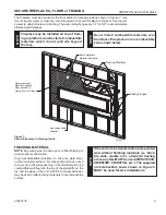
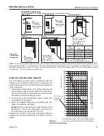
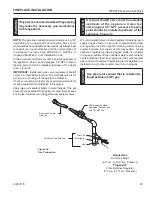
If the foundation is recessed, use recess brackets (not
supplied) for securing lower portion of the snorkel. Fasten
brackets to wall first, then secure to snorkel with self drill-
ing #8 x 1/2" sheet metal screws. It will be necessary to
extend vent pipes out as far as the protruding wall face.
Figure 23
FP1966
snorkel
Figure 23 -
Snorkel Installation, Recessed Foundation
Foundation
Recess
Watertight Seal
Around Pipe
Sheet Metal
Screws
Wall Screws
Snorkel
W
arn
In
G
•
Do not back fill around snorkel.
•
a clearance of at least 4" must be
maintained between the snorkel and
the soil.