background image

4

73D0024

KHLDV Series Gas Fireplace

IMportant SaFety InForMatIon and coDe approVaL

12.  Do not use this fireplace to cook food or burn paper or 

other objects.

13. Never place anything on top of fireplace.
14. Do not use any solid fuels (wood, coal, paper, card-

board,  etc.)  in  this  fireplace.  Use  only  the  gas  type 

indicated on rating plate.

15. This  appliance,  when  installed,  must  be  electrically 

grounded  in  accordance  with  local  codes  or  in  the 

absence  of  local  codes,  with  the 

National  Electrical 

Code, ANSI/NFPA 70

, or the 

Canadian Electrical Code, 

CSA C22.1.

16. Do not obstruct the flow of combustion and ventilation 

air in any way. Provide adequate clearances around 

air openings into the combustion chamber along with 

adequate  accessibility  clearance  for  servicing  and 

proper operation.

17. When the appliance is installed directly on carpeting, 

tile or other combustible material other than wood floor-

ing, you must set appliance on a metal or wood panel 

or hearth pad extending the full width and depth of the 

appliance.

18. Do not use fireplace if any part has been exposed to 

or has been under water. Immediately call a qualified 

service technician to inspect the appliance and replace 

any part of the control system and any gas control which 

as been submerged in water.

19. Do not operate fireplace if any log is broken.
20. Do not use a blower insert, heat exchanger insert, or 

any  other  accessory  not  approved  for  use  with  this 

fireplace.

21. Do not operate the fireplace with glass door removed, 

cracked, or broken.

coDe approVaL 

Direct Vent type appliances draw all combustion air from 

outside of the dwelling through the vent pipe.
These appliances have been tested by CSA and found to 

comply with the established standards for DIRECT VENT 

GAS FIREPLACE HEATERS in the USA and Canada as 

follows:

LISteD VenteD GaS FIrepLace Heater

TESTED TO: ANSI Z21.88-2009 / CSA 2.33-2009 

STANDARDS

A manufactured home (USA only) or mobile home OEM 

installation  must  conform  with  the 

Manufactured Home 

Construction and Safety Standard,


title 24 cFr, part 

3280, 

or  when  such  a  standard  is  not  applicable,  the 

Standard for Manufactured Home Installations, anSI/

ncSBcS a225.1

, or 

Standard for Gas equipped recre-

ational Vehicles and Mobile Housing, cSa Z240.4

WARNING

!

HOT GLASS WILL

CAUSE BURNS.

DO NOT TOUCH GLASS

UNTIL COOLED.

NEVER ALLOW CHILDREN

TO TOUCH GLASS.

AVERTISSEMENT

!

Un panneau vitré chaud

 peut 

causer des brûlures.

Laissez refroidir le panneau

vitr

é

 avant d’y toucher.

Ne laisser jamais

 les enfants

toucher le panneau vitr

é

.

w

arn

In

G

never  connect  unit  to  private  (non-

utility) gas wells.  this gas is commonly 

known as wellhead gas.

IMportant:

pLeaSe reaD tHe FoLLowInG 

careFuLLy 

It is normal for fireplaces fabricated of steel to give off 

some expansion and/or contraction noises during the 

start up or cool down cycle. Similar noises are found with 

your furnace heat exchanger or car engine. 

IMportant:

pLeaSe reaD tHe FoLLowInG 

careFuLLy 

It is not unusual for gas fireplaces to give off some odor 

the first time it is burned. This is due to the manufacturing 

process. 

please ensure that your room is well ventilated 

during burn off — open all windows.

It is recommended that you burn your fireplace for at 

least ten (10) hours the first time you use it. Place the 

fan switch in the “OFF” position during this time.

Содержание KHLDV400

Страница 1: ... qualified installer service agency or the gas supplier This appliance may be installed in an aftermarket permanently located manufactured home USA only or mobile home where not prohibited by local codes This appliance is only for use with the type of gas indicated on the rating plate This appliance is not convertible for use with other gases unless a certified kit is used Aftermarket Completion o...

Страница 2: ...ure Signature Command 30 Electrical Installation Signature Command 30 Electrical Wiring 30 Junction Box Wiring 31 Command Center Wall Installation 31 Wall Switch Installation 31 Signature Command Wiring Diagram 32 Fan Blower Systems Signature Command 33 Operating Instructions Signature Command 34 Operating Instructions 35 To Turn Off Gas 35 Signature Command System Operation Instructions 36 Touch ...

Страница 3: ...reference IMPORTANT SAFETY INFORMATION This fireplace is a vented product This fireplace must be properly installed by a qualified service person The glass door must be properly seated and sealed If this unit is not properly installed by a qualified service person with glass door properly seated and sealed combustion leakage can occur CARBON MONOXIDE POISONING Early signs of carbon monoxide poison...

Страница 4: ...liances draw all combustion air from outside of the dwelling through the vent pipe These appliances have been tested by CSA and found to comply with the established standards for DIRECT VENT GAS FIREPLACE HEATERS in the USA and Canada as follows LISTED VENTED GAS FIREPLACE HEATER TESTED TO ANSI Z21 88 2009 CSA 2 33 2009 STANDARDS A manufactured home USA only or mobile home OEM installation must co...

Страница 5: ... are certified without deration for elevations up to 4 500 feet 1 370 m above sea level For elevations above 4 500 feet 1 370 m in USA installations must be in accordance with the current ANSI Z223 1 NFPA 54 and or local codes having juris diction In Canada please consult provincial and or local authori ties having jurisdiction for installations at elevations above 4 500 feet 1 370 m Natural Propa...

Страница 6: ... zn 1119 mm H 23M 606 mm 23M 606 mm 24Z v 616 mm I 44C 1127 mm 44C 1127 mm 50B zn 1278 mm J 8 zn 218 mm 8 zn 218 mm 8 zn 218 mm K 4Z v 108 mm 4Z v 108 mm 4Z v 108 mm L 4 102 mm 4 102 mm 4 102 mm M 38M zn 976 mm 38M zn 976 mm 44M zn 1129 mm N 1 25 mm 1 25 mm 1 25 mm Framing Dimensions O 44C v 1137 mm 44C v 1137 mm 50 zn 1284 mm P 45B zn 1153 mm 49B zn 1253 mm 55Z x 1410 mm Q 23M 606 mm 23M 606 mm 2...

Страница 7: ...LD CLIMATE INSULATION If you live in a cold climate seal all cracks around your appliance and wherever cold air could enter the room with noncombustible material It is especially important to insulate the outside chase cavity between the studs and under the floor on which the appliance rests if the floor is above ground level firebox framing Firebox framing can be built before or after the applian...

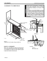
Страница 8: ...ct the front opening of the fireplace Do not install in the vicinity where gasoline or other flammable liquids may be stored Vent pipe routing Refer to the Venting section found in this manual for allowable venting configurations These units can be installed in a bedroom See National Fuel Gas Code ANSI Z233 1 NFPA 54 current edition the Uniform Mechanical Code current edi tion and Local Building C...

Страница 9: ...ese instructions carefully to ensure safe installation Failure to follow instructions exactly can create a fire hazard Theappliancecannotbeinstalledonacarpet tile or other combustible material other than wood flooring If installed on carpet or vinyl flooring the appliance shall be installed on a metal wood or noncombustible material panel extending full width and depth of the appliance FP2128 12 3...

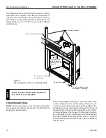
Страница 10: ...anels All Combustible Materials Must Keep 3 4 Spacing Nailing Flange FP2130 Figure 6 Secure Fireplace to Floor and Framing Studs Finishing Material NOTE Any remote wiring i e remote control wall switch and optional fan must be done prior to final finishing to avoid costly reconstruction Only noncombustible materials i e brick tile slate steel or other materials with a UL fire rating of Zero may be...

Страница 11: ...ould result in serious injury property damage or loss of life NOTICE Failure to follow these instructions will void the warranty WARNING This fireplace must be vented to the outside The venting system must NEVER be attached to a chimney serving a separate solid fuel burning appliance Each gas appliance must use a separate vent system Do not use common vent systems WARNING Horizontal sections of th...

Страница 12: ...ding type to building type These instructions are not substitutes for the requirements of local building codes You must follow all local building codes NOTICE When installing in a chase you should insulate the chase as you would the outside walls of your home This is especially important in cold climates Insulation should be considered a combustible material Maintain proper clearances to all combu...

Страница 13: ...above meter regulator assembly above the meter regulator assembly 5 m above the meter regulator assy I Clearance to service regulator vent outlet 3 91 cm 3 91 cm J Clearance to nonmechanical air supply inlet 6 15 cm for appliances 10 000 6 15 cm for appliances to building or the combustion air inlet to any BTU h 3kW 12 30 cm for 10 000 BTU h 3kW 9 other appliances appliances 10 000 BTU h 3kW and 2...

Страница 14: ...shed outside wall to the center of the pipe on the fireplace Vertical Dimension From the Floor of Unit to the Center of the Horizontal Vent Pipe Outside Corner Inside Corner Termination Clearances Termination clearances for buildings with combustible and noncombustible exteriors G Combustible 6 152 mm Noncombustible 2 51 mm F Combustible 6 152 mm Noncombustible 2 51 mm G Balcony with no side wall ...

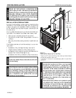
Страница 15: ...sition Measure the vertical height X required from the base of the flue collars to the center of the wall opening Figure 12 Step 4 Using appropriate length of pipe section s attach to fire place with three 3 screws Follow with the installation of the elbow Step 5 Measure the horizontal length requirement figuring a 1Z v 32 mm overlap i e from the elbow to the outside wall cap Figure 13 X X Figure ...

Страница 16: ... minimizes the number of offsets and horizontal vent length The horizontal vent run refers to the total length of vent pipe from the flue collar of the fireplace or the top of the Transition Elbow to the face of the finished outside wall The maximum number of 90 elbows per side wall installation is three 3 Figure 14 FP1176 Figure 14 Maximum Three 3 90 Elbows Per Installation 3 x 90 Elbows 24 Min F...

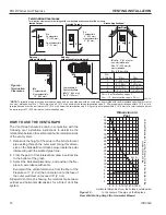
Страница 17: ...d proper drainage to be installed around the termination area If installing a snorkel a minimum 24 vertical rise is neces sary The maximum horizontal run with the 24 vertical pipe is 36 This measurement is taken from the collar of the fireplace or transition elbow to the face of the exterior wall See the Sidewall Venting Graph for extended horizontal run if the vertical exceeds 24 1 Establish vent...

Страница 18: ...183 max height 40 Maximum Height 12 Minimum Height 10 Maximum Support Straps Every 3 24 Min FP1183 Figure 21 Support Straps for Horizontal Runs vertical through the roof applications Install restrictor disc as shown in Figure 20 for vertically vented applications Up to two 2 restrictor discs may be needed for 40 instal lation The two 2 restrictor discs suppled will work for most instal lations If ...

Страница 19: ...to combustibles when passing through ceilings walls roofs enclosures attic rafters etc Do not pack air spaces with insulation Also note maximum vertical rise of the venting system and any maximum horizontal offset limitations Offsets must fall within the parameters shown in Figures 22 and 23 2 Set fireplace in desired location Drop a line plumb down from the ceiling to the position of the flue exi...

Страница 20: ...oof to lowest discharge opening of vent 4 Connect a section of pipe and extend up through the hole NOTE If an offset is needed to avoid obstructions you must support the vent pipe every three 3 feet Use wall straps for this purpose Refer to Page 18 Figure 21 Whenever possible use 45 elbows instead of 90 elbows The 45 elbow offers less restriction to the flow of the flue gases and intake air 5 Plac...

Страница 21: ...g gas pressure to between 11 and 13 inches of water If you do not reduce incoming gas pressure burner system regula tor damage could occur Install external regulator with the vent pointing down as shown in Figure 27 Pointing the vent down protects it from freezing rain or sleet WARNING A qualified installer or service person must connect appliance to gas supply Follow all local codes CAUTION For p...

Страница 22: ...ves Natural Gas From Gas Meter 4 5 w c to 10 5 w c Pressure Propane LP From External Regulator 11 w c to 13 w c Pressure 3 Minimum FP1978 gas connection Figure 28 Gas Connection Cap Approved Flexible Gas Line CSA Design Certified Equipment Shutoff Valve with 1 8 NPT Tap Sediment Trap Drip Leg Tee Joint Pipe Nipple WARNING Only persons licensed to work with gas piping may make the necessary gas con...

Страница 23: ...ve turn captured screw counter clockwise 2 or 3 turns and then place tubing to pressure gauge over test point Turn unit to high Figure 29 After taking pressure reading be sure and turn captured screw clockwise firmly to reseal Do not over torque Check test points for gas leaks Figure 29 Gas Pressure Check at Gas Valve Pressure Test IN Pressure Test OUT HI LO Knob Pilot Adjustment Screw Electrical ...

Страница 24: ...ional Fan Blower System BLOT KHL important Always check local building codes This installation must comply with local regulations as well as the National Electric Code WIRING 1 Before installing the blower wire the receptacle into an electrical circuit This should be done before framing the fireplace Wire with minimum 60 C wire in accordance with prevailing codes 2 Remove the external junction box...

Страница 25: ... FP2136 8 Two screws are already mounted to each cover which would be utilized to mount the blower to the cover Unfasten the two screws and mount the blower bracket assemblies Figure 33 9 Consult blower wiring diagram and start the assembly Figures 31 34 It is helpful to wire the right blower the speed control the fan limit switch and the power cord first Then plug in the power cord to the junctio...

Страница 26: ...e louvered side panels provided with the blower kit by unfastening the four nuts for each cover door Do not overtighten or stud may break off Use three metal clip screws provided with kit to secure the wire assembly in the front beneath the access cover Figure 36 15 Install the speed control rheostat switch on the side above the existing one used for the light discard the plate sent with the switc...

Страница 27: ...r attempted repair may result in a fire or explosion D Do not use this appliance if any part of it has been under water Immediately call a qualified service technician to inspect the appliance and to replace any part of the control system and any gas control that has been under water for your safety read before lighting Lighting pilot for the first timE initial lighting Purge air from the supply l...

Страница 28: ...following locations Pipe from the gas supply line connection to the gas valve Burner connections Field made joints gas shutoff valve Pilot Factory made joints Each joint or connection All joints on valve and control body Lighting pilot for the first time millivolt OPERATING INSTRUCTIONs PILOT O F F P I L O T ON FP1935 control knob pilot WARNING If using a soap and water solution to test for leaks ...

Страница 29: ... to light the main burner Lighting the burner Depress and turn the knob counterclockwise to the ON position It will take less than four 4 seconds for the burner to ignite Pilot position Depress and turn knob to pilot position to keep burner off while maintaining the pilot light Depress and turn knob clockwise to OFF position to turn off gas Off Position Pilot Position PILOT O F F PILOT O N O F F P...

Страница 30: ...lace is equipped with the Signature Control valve which operates on 6 volts The AC adapter plugs into the fireplace junction box A C power supply Four 4 AA batteries are used for back up during power outages 2 The Signature Command System can also be operated without A C power The system can run on four 4 AA batteries for approximately six 6 months under normal use 3 A C power must be used to powe...

Страница 31: ... not extend beyond the 15 ft wire cable provided If a longer distance is required the 15 ft may be extended up to 30 ft maximum by using two 2 SCSWEK cables plugged together Route the wire from junction box to lower control area at bottom of fireplace Unplug the 12 cable from the command center Attach the connector to the pins from wire by pushing in to connector making sure to follow the color co...

Страница 32: ...n Connector Control Board to Solenoid Gas In Gas Out Pilot Gas Tubing Valve A C Module FP2704 SCS wiring diagram To Outlet Light 300 Watt Max Optional Blower 300 Watt Max Rear Burner Solenoid 300 Watt Max ELECTRICAL INSTALLATION CAUTION Electrical connections should only be performedbyaqualified licensedelectrician Main power supply must be turned off before connecting fans to the main electrical ...

Страница 33: ...ectly WARNING Electrical connections should only be performed by a qualified licensed electrician Main power supply must be turned off before connecting the fan to the main electrical power supply or performing service BLOTKHLSC SIGNATURE COMMAND BLOWER Electrical Grounding Instructions This appliance is equipped with a three prong grounding plug for your protection against shock hazard and should...

Страница 34: ...s phone Follow the gas supplier s instructions If you cannot reach your gas supplier call the fire department C Use only your finger to push in the master switch Never use tools If the switch will not function by hand do not try to repair it Call a qualified service technician Force or attempted repair may result in a fire or explosion D Do not use this appliance if any part of it has been under w...

Страница 35: ... gas go to next step 4 Press the master switch to the ON position Within eight 8 seconds it will beep once This indicates the system is ready 5 Press ON button Sparker will spark and pilot flame will light 6 Once pilot flame is established the main burner flame will light automatically 7 If the pilot will not stay lit after several tries turn the master switch to OFF and call your service technici...

Страница 36: ... Lock out X LCD Backlight X Security Codes 16 X Countdown 6 hr Timer X Standard Thermostatic Control Mode X Smart Mode Thermostat Auto Flame Blower Modulation X Three Brightness Settings for Lights X Three Speed Control for Blower X On Off AUX Rear Burner X Programmable Timer to turn blower on and off X BATTERY INSTALLATION The Command Center uses four 4 AA batteries as back up for power outages T...

Страница 37: ...n stand ing pilot and intermittent pilot 2 After the above operation one beep for standing pi lot or two beeps for intermittent pilot will be given as confirmation Six hour Safety Shutdown Option Default ON 1 The system comes preset from the factory with a six 6 hour shutdown from its last command of operation This is done to prevent the fireplace from continuing to operate if unattended You may d...

Страница 38: ...oblems and potentially avoid a service call Please refer to the charts below for indica tor reference Function Operation Power Up Flip the master switch to the ON _ position to power up the system Fireplace ON Press the ON button on the Command Center or turn on wall switch to turn the fireplace on Fireplace OFF Flip the master switch to the OFF o position OR press the OFF button 3 times OR for Me...

Страница 39: ...ws The blue LED backlight lights up for 8 seconds when any of the touch buttons is pressed The menus include TIMER THERMO LIGHT FAN and AUX Rear Burner Control The adjustment arrows include ON up and OFF down Their default function is to adjust the flame height When a button from the menu is pressed the ON up and OFF down buttons will temporarily become adjustment controls for the selected item Wh...

Страница 40: ...en and the green LED on the Command Center will flash for 10 seconds 4 During the 10 seconds press the OFF button on the transmitter to learn Another two beeps will be given to confirm a successful learning Figure 47 FP2649 set privace code Figure 45 FP2650 command ctr ctrl brd Battery Door Master Switch ON LED OFF FP2650 Command Center Figure 47 WARNING Do not use two 2 or more remote control sys...

Страница 41: ...de In both modes the fireplace will be shut down completely when the timer counts down to zero 6 To exit Timer Mode a Push and hold the TIMER button for 3 seconds Or b Use the OFF down buttons to decrease the Set Time to zero Or c Slide down on the arrow buttons to exit TIMER mode and shut off the fire place Thermostat Mode Figure 50 Press the THERMO button to set the transmitter in thermostat mod...

Страница 42: ...ng 2 Press the ON up and OFF down button to increase de crease the blower speed 3 Press the fan button again to confirm the speed set ting If the fireplace is on the blower speed will take effect right away if the fireplace is off the receiver will remember this setting and the blower is still off see blower On Delay and Off Delay in the next section 4 After the signal is sent the ON up and OFF do...

Страница 43: ...ght controller again 5 When the light button is flashing slide up and down on the arrow buttons will turn the light brightness to HIGH or Off directly without pressing the light button again to confirm AUX Control Rear Burner On Off Control TheAUX control function is used to turn on or turn off the rear burner connected to the AC module of the Signature Command System Press the AUX button to turn ...

Страница 44: ...Check battery installation or replace batteries 3 LCD display shows funny display 3 Reset the transmitter see Resetting the Transmitter section 4 Appliance does not come on 2 The transmitter did not match 1 Make sure the transmitter has with the receiver learned to the receiver 3 Transmitter measures temp 1 Move transmitter to a cooler place erature exceeding 99 degrees and wait until temperature ...

Страница 45: ...of the glass toward the glass 4 Remove glass frame by releasing the three latches located at the top of the firebox Tilt glass away from the unit lift glass frame up and away from the unit Figure 57 FP2153 remove glass frame Figure 57 Remove Glass Frame Glass Frame FP2153 CAUTION Each clamp has a quick spring force When reinstalling clamps keep fingers clear WARNING HOT GLASS WILL CAUSE BURNS DO N...

Страница 46: ...ovided in the kit 6 Place the front hearth brick simultaneously and pull toward the front away from the burner This is critical for balancing air flow around the front burner 7 Install the halogen light bulb provided with the unit inside the log set Do not touch light bulb directly with fingers 8 Replace the trapezoidal light shroud removed in step 1 by sliding it over the light bulb and sockets B...

Страница 47: ...ight unit and after 15 minutes check burner flame and glow Refer to Burner Flame Page 53 FP2155 ember placement FP2155 Figure 61 Rockwool placement 400 500 Series WARNING Do not use the entire bag of rock wool to cover the burner This could cause the flame to burn poorly and may lead to sooting final installation ROCK WOOL PLACEMENT 600 SERIES Place rock wool evenly in dime sized pieces over front...

Страница 48: ...the log with the wide end toward the back and the branch toward the front and left Set the log by having the protrusion on the bottom of the log rest to the left side of the grate bar and behind the pilot shield Also set the notch located at the bottom of the left branch over the second right tong on the grate Make sure that the log is positioned properly so it is not rocking NOTE When the log is ...

Страница 49: ... surface of the middle log When this log is in place the pointed end will come in contact with the back of the pilot log placed in step 2 Step 6 LG599 KHLDV upper right log LG599 6 Place the right upper log over the pilot log and the hearth brick by matching the indentation on the bottom of the log with the protrusion on the pilot log LG600 KHLDV upper right rear log LG600 7 Place the upper right ...

Страница 50: ... SERIES 1 Hold log 1 with the key to the top and to the right side of center and the notches on the bottom Place the log with the notches over the side supports of the grate in front of the flame bracket on the left and with the small notch in the lower right front of the log resting on the back of the right tine of the grate LG918 LG919 LG920 600 Log 2 2 Hold log 2 with the holes for the pin in t...

Страница 51: ... 4 with the notch on the bottom and toward the back of the unit Place the left end of the log on the key provided on the top of log 3 Rest the right end of the log on the hearth brick just to the right end of log 1 5 Hold log 5 with the fat end of the log to the left and the detailed face of the log to the front Place the notch on the bottom right end of the log onto the key provided on the top of...

Страница 52: ... and log 3 in the back NOTE Log 6 will help to hold log 5 in place 7 Hold log 7 with the pointed end to the left and the notch on the bottom Place the pointed end of the log on the hearth brick in front of the burner and under the third time from the right Rest the notch on the bottom middle of the log on the bend of the second tine from the right Slightly rotate the log forward The right end of t...

Страница 53: ... logs clean by vacuuming or brushing at least twice a year Make sure the burner porting pilot air opening and burner air opening are free of obstructions at all times Pilot Flame The flames from the pilot should be visually checked as soon as the heater is installed and periodically during normal operation The pilot flame must always be pres ent when the fireplace is in operation Figure 61 The pil...

Страница 54: ...als may be used Handle glass door with care to avoid striking or scratch ing it on hard objects To clean glass door follow Glass Removal procedure outlined in the Final Installation section Film deposit on the inside of the glass should be cleaned off using a nontoxic non corrosive non abrasive mild cleaning solution Simply apply an adequate amount to the glass and wipe off with a damp cloth After...

Страница 55: ...thermocouple connection at the gas valve is fully inserted and tight Disconnect the thermocouple from the valve place one millivolt lead wire on the tip of the thermocouple and the other meter lead wire on the thermocouple copper lead Start the pilot and hold the valve knob in If the millivolt reading is less than 15 mV replace pilot assembly B If thermocouple is producing more than 15 mV replace ...

Страница 56: ...the pilot flame for maximum flame impingement on thermocouple A Check for flue product leak Replace defective pipe section B Check horizontal venting piping is running upward 1 4 per foot Do not run the pipe level or downward C Check for proper installation and freedom from debris or blockage A Install log set per the instructions Inspect the injector and air intake area Make sure this area does n...

Страница 57: ...gh Battery polarity wrong LED on the Command Center does not show solid green The 5 pin connector on the AC board broken or bent AC plug is plugged to AC mains Battery voltage low Using battery Check valve connections Check power supply go through A E Check grounding Go through B Go through C The sensor on the pilot is not in the flame pilot flame too small ACTION Re install batteries Change batte...

Страница 58: ... Series 1 73D0022 73D0022 5 Light Lens 600 Series 2 73D4057 6 Panel Access Door 2 73D0029K 73D0029K 73D0092 7a Firebrick Set Tavern Brown 1 FBKHLDV400TB FBKHLDV500TB FBKHLDV600TB 7b Firebrick Set Cottage Red 1 FBKHLDV400CR FBKHLDV500CR FBKHLDV600CR 8 Firebrick Set Old English Herringbone 1 FBKHLDV400OE FBKHLDV500OE FBKHLDV600OE 9 Screen Rod 1 73D0010 73D0010 20300611 10 Screen 2 73D0017 73D0017 20...

Страница 59: ...73D0024 59 KHLDV Series Gas Fireplace REPLACEMENT PARTS Standing Pilot Millivolt control 1 3 4 5 6 7 8 2C 2I 2T 2 10 11 12 13 14 730024 khldv mv valve parts ...

Страница 60: ...0030 69D0030 69D0030 69D0030 5 Rocker Switch 1 41D0048 41D0048 41D0048 41D0048 6 Piezo Igniter 1 14D0503 14D0503 14D0503 14D0503 7 Rear Injector 1 58D0102 58D0052 57D0679 57D0680 7 Front Injector 1 57D0612 58D0056 56D3059 62D3005 8 Rear Burner Assembly 1 73D3270 73D3270 73D2368 73D3268 8 Front Burner Assembly 1 73D3269 73D3269 73D3267 73D3267 9 Venturi 1 45D0600 45D0600 45D0600 45D0600 10 Wire Ass...

Страница 61: ...ries 8b 8a 2 Shield Pilot 1 4 Venturi Gasket 3 14 9 7b 7a 5b 5a 5d 5e 15 5c 6 Flex Hose 20H0022 500 Series 8b 8a Shield Pilot 2 1 3 Venturi Gasket 9 7b 5b 5e 3 14 7a 5a 5d 6 Flex Hose 20H0022 15 5c 600 Series 17 18 17 18 13 13 8a 2 9 7a 5a 5b 7b 8b 1 6 Flex Hose 20H0022 4 3 14 15 5f 5g 16 ...

Страница 62: ...6 56D3059 62D3005 20H3155 20H3146 8a Rear Burner Assembly 1 73D3270 73D3270 73D3268 73D3268 20302746 20300556 8b Front Burner Assembly 1 73D3269 73D3269 73D3267 73D3267 20300555 20300555 9 Venturi 1 69D1026 69D1026 69D1026 69D1026 69D1026 69D1026 10 Wire Valve Control Board SCS 1 80D0010 80D0010 80D0010 80D0010 80D0010 80D0010 not shown 11 Wire AC Module SCS not shown 1 80D0009 80D0009 80D0009 80D...

Страница 63: ...og 1 1 73D0539 73D0200 20301946 2 Log 2 1 73D0540 73D0201 20301947 3 Log 3 1 73D0541 73D0202 20301948 4 Log 4 1 73D0542 73D0203 20301949 5 Log 5 1 73D0543 73D0204 20301950 6 Log 6 1 73D0544 73D0205 20301951 7 Log 7 1 73D0545 73D0206 20301952 KHLDV400 KHLDV500 LOGS 730024 600 log parts 1 2 3 4 5 6 7 KHLDV600 LOGS ...

Страница 64: ...64 73D0024 KHLDV Series Gas Fireplace HOT 1 2 3 4 5 6 9 7 8 10 730024 KHLDV vent parts VENTing components REPLACEMENT PARTS ...

Страница 65: ...ical Termination see below see below 5DT VC 5DVT 2 1 Extended Vertical Termination 58DVA VCE 1283 2 1 High Wind Vertical Termination 58DVA VCH 1291 3 4 6 Pipe Length 58DVA 06 1208 5DT 06 5D6 3 4 9 Pipe Length 58DVA 09 1207 5DT 09 3 4 12 Pipe Length 58DVA 12 1206 5DT 12 5D12 3 4 24 Pipe Length 58DVA 24 1204 5DT 24 5D24 3 4 36 Pipe Length 58DVA 36 1203 5DT 36 5D36 3 4 48 Pipe Length 58DVA 48 1202 5D...

Страница 66: ...cordance with the above provisions shall comply with NFPA 720 and ANSI UL 2034 listed and IAS certified Signage A metal or plastic identification plate shall be permanently mounted to the exterior of the building at a minimum height of eight 8 feet above grade directly in line with the exhaust vent terminal for the horizontally vented gas fueled heating appliance or equipment The sign shall read i...

Страница 67: ...Limited Lifetime Warranty will also be void if the appliance is not operated and maintained according to the operating instructions supplied with the appliance and does not extend to 1 firebox burner assembly damage by accident neglect misuse abuse alterations negligence of others including the installation thereof by unqualified installers 2 the costs of removal reinstallation or transportation o...

Страница 68: ...elon CSA P 4 1 09 Efficiency Ratings Model EnerGuide Ratings Fireplace Efficiency KHLDV400NV 69 6 KHLDV400PV 78 2 KHLDV400NTSC 73 2 KHLDV400PTSC 82 2 KHLDV500NV 75 2 KHLDV500PV 69 8 KHLDV500NTSC 78 5 KHLDV500PTSC 71 8 KHLDV600NTSC 81 0 KHLDV600PTSC 80 0 Vermont Castings Group 149 Cleveland Drive Paris Kentucky 40361 www vermontcastingsgroup com ...

Отзывы: