32
73D0024
KHLDV Series Gas Fireplace
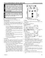
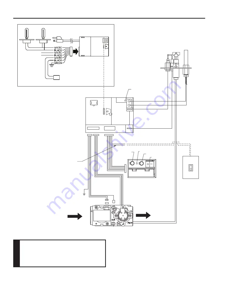
A/C Module
Control Board
RF Receiver
ON/OFF Button
Pilot
Black / Thermopile
Red / Thermopile
Sensor
Ignitor / Sparker
Conversion
NG/LP
Plug-in Connector
Control Board to Command Center
OFF/LO
LED
ON/HI
Master Switch
Command Center
Optional
Wall Switch
Plug-in Connector
Stepper Motor to
Control Board
DC Power/Green
Ground
Plug-in Connector
Control Board to
Solenoid
Gas In
Gas Out
Pilot Gas Tubing
Valve
A/C Module
FP2704
SCS wiring diagram
To Outlet
Light
300 Watt
Max
Optional Blower
300 Watt
Max
Rear Burner Solenoid
300 Watt Max
eLectrIcaL InStaLLatIon
caut
Ion
electrical connections should only be
performed by a qualified, licensed electrician.
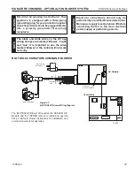
Main power supply must be turned off before
connecting fans to the main electrical power
supply or performing service.
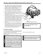
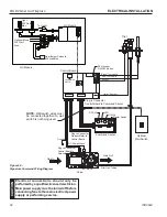
Figure 40 -
Signature Command Wiring Diagram
note:
Wall switch wires must
be connected together if a wall
switch is not being used.

