background image

Installation

812.0061

9

Fluid Suction and Outlet Lines

For best sealing results, use a standard tri-clamp or DIN 

style sanitary gasket of a flexible material such as 

EPDM, Buna-N, fluoroelastomer, or silicone.

NOTE: 

Compliance with 3A sanitary standards requires 

DIN connections to use certain gaskets. See CCE 

Coordination Bulletin Number 2011-3. 

1. Install flexible, conductive fluid lines (G and H). 

2. Install a fluid drain valve (K) close to the pump fluid 

outlet. See F

IG

. 2.

3. Install a fluid shutoff valve (J) in the fluid outlet line 

(G) downstream from the fluid drain valve (K).

NOTE: 

For best results, always install the pump as 

close as possible to the material source. See the 

Technical Data

 for maximum suction lift (wet and dry). 

Tips to Reduce Cavitation

Cavitation in a diaphragm pump is the formation and 

collapse of bubbles in the pumped liquid. Frequent or 

excessive cavitation can cause serious damage, 

including pitting and early wear of fluid chambers, balls, 

and seats. It may result in reduced efficiency of the 

pump. Cavitation damage and reduced efficiency both 

result in increased operating costs.
Cavitation depends on the vapor pressure of the 

pumped liquid, the system suction pressure, and the 

velocity pressure. It can be reduced by changing any of 

these factors.
1. Reduce vapor pressure: Decrease the temperature 

of the pumped liquid.

2. Increase suction pressure:

a. Lower the installed position of the pump relative 

to the liquid level in the supply.

b. Reduce the friction length of the suction lines. 

Remember that fittings add friction length to the 
lines. Reduce the number of fittings to reduce 
the friction length.

c. Increase the diameter of the suction lines.

d. Ensure the inlet fluid pressure does not exceed 

25% of the outlet working pressure.

3. Reduce liquid velocity: Slow the cyclic rate of the 

pump.

Pumped liquid viscosity is also very important but 

normally is controlled by factors that are process 

dependent and cannot be changed to reduce cavitation. 

Viscous liquids are more difficult to pump and more 

prone to cavitation.

Verder recommends taking all of the above factors into 

account in system design. To maintain pump efficiency, 

supply only enough air to the pump to achieve the 

required flow.

Verder distributors can supply site-specific suggestions 

to improve pump performance and reduce operating 

costs.

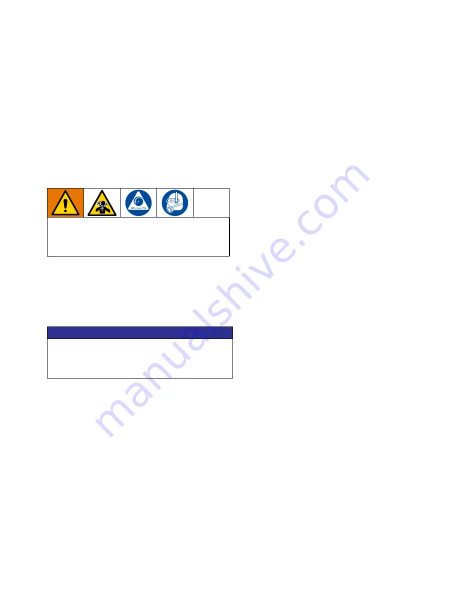
A fluid drain valve (K) is required to relieve pressure 

in the fluid outlet line if it is plugged. The drain valve 

reduces the risk of serious injury, including splashing 

in the eyes or on the skin, when relieving pressure.

NOTICE

The pump can be damaged if flexible fluid lines are 

not used. If hard-plumbed fluid lines are used in the 

system, use a short length of flexible, conductive fluid 

line to connect to the pump.

Содержание HI-CLEAN VA-2H25

Страница 1: ...eres or hazardous classified locations unless otherwise stated See Approvals page for more information For professional use only 8 bar 0 8 MPa 120 psi Maximum Fluid Working Pressure 8 bar 0 8 MPa 120 psi Maximum Air Input Pressure Important Safety Instructions Read all warnings and instructions in this manual before using the equipment Save these instructions 812 0061 Rev A EN ...

Страница 2: ...tions 15 VA 2H25 Dimensions 15 VA 2H25 Performance Chart 16 VA 2H25 Technical Data 17 VA 2H40 Specifications 18 VA 2H40 Dimensions 18 VA 2H40 Performance Charts 19 VA 2H40 Technical Data 21 VA 2H52 Specifications 22 VA 2H52 Dimensions 22 VA 2H52 Performance Chart 23 VA 2H53 Specifications 24 Vertical VA 2H53 Dimensions 24 Horizontal VA 2H53 Dimensions 25 VA 2H53 Performance Chart 26 VA 2H54 Specif...

Страница 3: ...nding instructions Keep work area free of debris including solvent rags and gasoline Do not plug or unplug power cords or turn power or light switches on or off when flammable fumes are present Use only grounded fluid lines Hold gun firmly to side of grounded pail when triggering into pail Do not use pail liners unless they are anti static or conductive Stop operation immediately if static sparkin...

Страница 4: ... Call your distributor for information Route fluid lines and cables away from traffic areas sharp edges moving parts and hot surfaces Do not kink or over bend fluid lines or use fluid lines to pull equipment Keep children and animals away from work area Comply with all applicable safety regulations TOXIC FLUID OR FUMES HAZARD Toxic fluids or fumes can cause serious injury or death if splashed in t...

Страница 5: ...aterial Air Section Material Seat Material VA 2H 25 25 mm X High Sanitation 3 A 0 8 μm E Polished Stainless Steel SB Stainless Steel Buna N gasket 40 40 mm SE Stainless Steel EPDM gasket 52 50 mm 2 inch ports Y Pharmaceutical 0 5 μm S Stainless Steel ST Stainless Steel EP TF gasket 53 50 mm 3 inch ports SV Stainless Steel FKM gasket 54 50 mm 4 inch ports Ball Material Diaphragm Material Connection...

Страница 6: ...ply with EC 1935 2004 Diaphragm materials coded EO or TS combined with flapper or TF ball checks comply with Class VI All models are approved to All fluid contact materials are FDA compliant and meet the United States Code of Federal Regulations CFR Diaphragm Ball Seat Material Fluid Temperature Range Fahrenheit Celsius Buna N 10 to 180 F 12 to 82 C FKM Fluoroelastomer 40 to 275 F 40 to 135 C EPDM...

Страница 7: ...ecurely Connect the clamp end of the ground wire to a true earth ground To order a ground wire and clamp order part number 819 0157 X W TI4736A FIG 1 Ground Wire Connection Air and fluid lines Use only conductive lines with a maximum of 150 m 500 ft combined line length to ensure grounding continuity Check electrical resistance of lines If total resistance to ground exceeds 29 megohms replace line...

Страница 8: ...ies is properly grounded a Install an air regulator B and air pressure gauge T to control the air pressure Reducing the supplied air pressure will reduce the pump s fluid outlet pressure b Locate one bleed type master air valve C close to the pump and use it to relieve trapped air Locate the other master air valve A upstream from all air line accessories and use it to isolate them during cleaning ...

Страница 9: ...Reduce vapor pressure Decrease the temperature of the pumped liquid 2 Increase suction pressure a Lower the installed position of the pump relative to the liquid level in the supply b Reduce the friction length of the suction lines Remember that fittings add friction length to the lines Reduce the number of fittings to reduce the friction length c Increase the diameter of the suction lines d Ensur...

Страница 10: ...D Air supply line E Air line coupler F 1 2 npt f pump air inlet G Flexible fluid outlet line H Flexible fluid suction line J Fluid shutoff valve required not supplied K Fluid drain valve required not supplied L Ground wire required not supplied see page 7 for installation instructions R Air line filter S Air pressure gauge required not supplied FIG 2 Typical Floor Mount Installation ...

Страница 11: ...onductive grounded container P at the end of the air exhaust line to catch fluid in case of a diaphragm rupture See FIG 3 FIG 3 Venting Exhaust Air Be sure the system is properly ventilated for your type of installation You must vent the pump air exhaust to a safe place away from people animals food handling areas and all sources of ignition when pumping flammable or hazardous fluids Diaphragm rup...

Страница 12: ... pump was built and tested using a food grade lubricant Properly sanitize the pump before first use The user must determine whether to disassemble and clean individual parts or simply flush the pump with a sanitizing solution To simply flush the pump with a sanitizing solution follow the steps under Start and Adjust the Pump page 13 and Flushing and Storage page 14 To disassemble and clean individ...

Страница 13: ...ng with the following step 8 To prime the pump slowly increase air pressure with the air regulator B until the pump starts to cycle Do not exceed the maximum operating air pressure as listed in the Technical Data pages 17 and 30 Allow the pump to cycle slowly until all air is pushed out of the fluid lines and fluid exits the outlet line G NOTE If the fluid inlet pressure to the pump is more than 2...

Страница 14: ...from the sanitizing solution and drain pump Routine Cleaning of Product Contact Section of Pump NOTE The pump and the system should be cleaned in accordance with applicable sanitary standard codes and local regulations 1 Flush the system See Flushing and Storage above 2 Follow the Pressure Relief Procedure page 12 3 If disassembly of the pump is required for cleaning refer to the appropriate repai...

Страница 15: ... Specifications 812 0061 15 VA 2H25 Specifications VA 2H25 Dimensions Ø 10 mm 0 40 in A 49 0 cm 19 3 in B 34 8 cm 13 7 in C 26 7 cm 10 5 in D 6 6 cm 2 6 in E 39 9 cm 15 7 in F 31 2 cm 12 3 in G 21 6 cm 8 5 in ...

Страница 16: ... 120 0 83 6 9 100 0 69 5 5 80 0 55 4 1 60 0 41 2 8 40 0 28 1 4 20 0 14 0 19 5 38 10 57 15 76 20 95 25 114 30 132 35 151 40 170 45 0 19 5 38 10 57 15 76 20 95 25 114 30 132 35 151 40 170 45 0 1 87 70 1 61 60 1 34 50 1 07 40 0 80 30 0 54 20 0 27 10 0 To find Fluid Outlet Pressure bar psi MPa at a specific fluid flow lpm gpm and operating air pressure bar psi MPa 1 Locate fluid flow rate along bottom...

Страница 17: ...XPSDEOH VROLGV LQ PP OXLG GLVSODFHPHQW SHU F FOH JDOORQV OLWHUV 0D LPXP IUHH ᚐRZ GHOLYHU JSP OSP 0D LPXP SXPS VSHHG FSP HLJKW OE NJ OXLG QOHW DQG 2XWOHW 6L H 6WDLQOHVV 6WHHO LQ VDQLWDU ᚐDQJH RU PP 1 PDOH WKUHDG 1RLVH DWD 6RXQG 3RZHU PHDVXUHG SHU 62 ದ DW EDU ᚐXLG SUHVVXUH IXOO ᚐRZ G D 6RXQG 3UHVVXUH DW EDU ᚐXLG SUHVVXUH DQG FSP G D DW EDU ᚐXLG SUHVVXUH IXOO ᚐRZ G D HWWHG 3DUWV HWWHG SDUWV LQFOXGH P...

Страница 18: ...tions 18 812 0061 VA 2H40 Specifications VA 2H40 Dimensions Ø 11 mm 0 43 in A 82 8 cm 32 6 in B 43 2 cm 17 0 in C 43 9 cm 17 3 in D 26 9 cm 10 6 in E 53 3 cm 21 0 in F 60 5 cm 23 8 in J 36 8 cm 14 5 in K 53 3 cm 21 0 in ...

Страница 19: ...7 8 3 120 0 83 6 9 100 0 69 5 5 80 0 55 4 1 60 0 41 2 8 40 0 28 1 4 20 0 14 0 0 76 20 151 40 227 60 303 80 379 100 454 120 AIR CONSUMPTION m 3 min scfm FLUID FLOW lpm gpm 1 61 60 1 07 40 0 54 20 0 3 21 120 2 68 100 2 14 80 4 28 160 3 75 140 To find Fluid Outlet Pressure bar psi MPa at a specific fluid flow lpm gpm and operating air pressure bar psi MPa 1 Locate fluid flow rate along bottom of char...

Страница 20: ...38 10 76 20 114 30 151 40 0 189 50 227 60 265 70 303 80 341 90 0 38 10 76 20 114 30 151 40 189 50 227 60 265 70 303 80 341 90 1 61 60 1 07 40 0 54 20 0 3 21 120 2 68 100 2 14 80 4 28 160 3 75 140 FLUID OUTLET PRESSURE bar psi MPa 4 82 180 VA 2H40 Specifications 20 812 0061 To find Fluid Outlet Pressure bar psi MPa at a specific fluid flow lpm gpm and operating air pressure bar psi MPa 1 Locate flu...

Страница 21: ...OLWHUV ᚐDSSHU JDOORQV OLWHUV 0D LPXP IUHH ᚐRZ GHOLYHU EDOO JSP OSP ᚐDSSHU JSP OSP 0D LPXP SXPS VSHHG EDOO FSP ᚐDSSHU FSP HLJKW HLJKW HLJKW EDOO OE NJ ᚐDSSHU OE OXLG OXLG OXLG QOHW QOHW QOHW DQG DQG DQG 2XWOHW 2XWOHW 2XWOHW 6L H 6L H 6L H 6WDLQOHVV 6WHHO LQ VDQLWDU ᚐDQJH RU PP 1 PDOH WKUHDG 1RLVH 1RLVH 1RLVH DWD DWD DWD 6RXQG 3RZHU PHDVXUHG SHU 62 ದ DW EDU SVL ᚐXLG SUHVVXUH IXOO ᚐRZ G D 6RXQG 3UHVV...

Страница 22: ...tions 22 812 0061 VA 2H52 Specifications VA 2H52 Dimensions Ø 11 mm 0 43 in A 90 7 cm 35 7 in B 49 0 cm 19 3 in C 43 9 cm 17 3 in D 19 1 cm 7 5 in E 68 6 cm 27 0 in F 60 5 cm 23 8 in J 36 8 cm 14 5 in K 53 3 cm 21 0 in ...

Страница 23: ... 4 1 60 0 41 2 8 40 0 28 1 4 20 0 14 0 76 20 151 40 0 227 60 303 80 379 100 454 120 530 140 606 160 681 180 757 200 FLUID OUTLET PRESSURE bar psi MPa 0 76 20 151 40 227 60 303 80 4 02 150 2 68 100 1 34 50 0 6 70 250 5 36 200 379 100 454 120 530 140 606 160 681 180 757 200 To find Fluid Outlet Pressure bar psi MPa at a specific fluid flow lpm gpm and operating air pressure bar psi MPa 1 Locate flui...

Страница 24: ... 24 812 0061 VA 2H53 Specifications Vertical VA 2H53 Dimensions Ø 11 mm 0 43 in A 100 3 cm 39 5 in B 52 1 cm 20 5 in C 43 9 cm 17 3 in D 11 4 cm 4 5 in E 84 3 cm 33 2 in F 60 5 cm 23 8 in J 36 8 cm 14 5 in K 53 3 cm 21 0 in ...

Страница 25: ...fications 812 0061 25 Horizontal VA 2H53 Dimensions Ø 0 53 in 13 5 mm G 50 5 cm 19 9 in H 56 9 cm 22 4 in J 35 6 cm 14 0 in K 38 6 cm 15 2 in L 138 4 cm 54 5 in L2 58 4 cm 23 0 in M 35 1 cm 13 8 in N 31 0 cm 12 2 in ...

Страница 26: ... 40 0 227 60 303 80 379 100 454 120 530 140 FLUID OUTLET PRESSURE bar psi MPa 0 76 20 151 40 227 60 303 80 379 100 454 120 530 140 AIR CONSUMPTION m 3 min scfm FLUID FLOW lpm gpm 4 02 150 2 68 100 1 34 50 0 6 70 250 5 36 200 To find Fluid Outlet Pressure psi MPa bar at a specific fluid flow gpm lpm and operating air pressure psi MPa bar 1 Locate fluid flow rate along bottom of chart 2 Follow verti...

Страница 27: ...ications 812 0061 27 VA 2H54 Specifications Vertical VA 2H54 Dimensions Ø 13 5 mm 0 53 in A 116 6 cm 45 9 in B 58 7 cm 23 1 in C 29 5 cm 11 6 in D 11 4 cm 4 5 in E 99 1 cm 39 0 in F 53 8 cm 21 2 in G 40 6 cm 16 0 in ...

Страница 28: ...fications 28 812 0061 Horizontal VA 2H54 Dimensions Ø 0 53 in 13 5 mm G 50 5 cm 19 9 in H 62 0 cm 24 4 in J 35 6 cm 14 0 in K 40 6 cm 16 0 in L 148 6 cm 58 5 in L2 60 2 cm 23 7 in M 35 1 cm 13 8 in N 31 0 cm 12 2 in ...

Страница 29: ...20 0 14 0 0 38 10 76 20 114 30 151 40 189 50 227 60 265 70 303 80 341 90 379 100 FLUID OUTLET PRESSURE bar psi MPa 0 38 10 76 20 114 30 151 40 189 50 227 60 265 70 303 80 341 90 379 100 4 02 150 2 68 100 1 34 50 0 6 70 250 5 36 200 AIR CONSUMPTION m 3 min scfm To find Fluid Outlet Pressure bar psi MPa at a specific fluid flow lpm gpm and operating air pressure bar psi MPa 1 Locate fluid flow rate ...

Страница 30: ... OSP 0D LPXP SXPS VSHHG 9 EDOO FSP 9 ᚐDSSHU FSP 9 ᚐDSSHU FSP HLJKWV HLJKWV HLJKWV 9DOXHV DUH IRU YHUWLFDO SXPSV KRUL RQWDO SXPSV VOLJKWO ORZHU 9 EDOO OE NJ 9 ᚐDSSHU OE NJ 9 ᚐDSSHU OE NJ OXLG OXLG OXLG QOHW QOHW QOHW DQG DQG DQG 2XWOHW 2XWOHW 2XWOHW 6L H 6L H 6L H VWDLQOHVV VWHHO 9 LQ VDQLWDU ᚐDQJH RU PP 1 PDOH WKUHDG 9 LQ VDQLWDU ᚐDQJH RU PP 1 PDOH WKUHDG 9 LQ VDQLWDU ᚐDQJH RU PP 1 PDOH WKUHDG 1RL...

Страница 31: ...chase price WARRANTY DISCLAIMER VERDER has made an effort to illustrate and describe the products in the enclosed brochure accurately however such illustrations and descriptions are for the sole purpose of identification and do not express or imply a warranty that the products are merchantable or fit for a particular purpose or that the products will necessarily conform to the illustration or desc...

Страница 32: ...chwad Pune 411019 INDIA e mail sales verder co in www verder co in Italy Verder Italia Via Maestri Del lavoro 5 02100 Vazia Rieti ITALY Tel 39 07 46 229064 e mail info verder it Korea Verder Korea 15 26 Beodeul ro 1362 Paltan myun Hwaseong si Gyeonggi do 18578 KOREA Tel 82 31 355 0316 e mail sales verder kr The Netherlands Verder BV Leningradweg 5 NL 9723 TP Groningen THE NETHERLANDS Tel 31 50 549...

Отзывы: