12
VUT R EH EC
VUT R EH EC
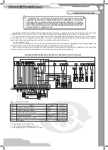
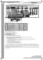
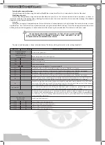
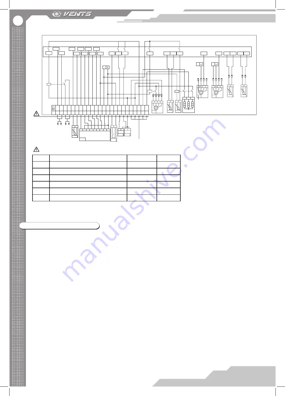
EXTERNAL WIRING DIAGRAM FOR THE UNITS VUT R 900 EH EC, VUT R 1200 EH EC AND VUT R 1500 EH EC
22
X1
21 20 19 18 17 16 15 14 13 12 11 10 9 8 7 6 5 4 3 2 1
no
14
t°C
C
CU ac
tivation sig
nal
(0-10 V
)
C
CU ac
tivation sig
nal
(no
-c
ontac
t / 16A
)
P
o
w
er supply
400 V
A
C
1
2
13 12 9 10 11 6
2
1
1
c
2 14 12 9 10
P1
11 6
SAS908PIT-V2-S1-F3
— ELECTRIC SHOCK HAZARD!
2 1 1 2 2 2 1 PE N L3 L2 L1
TE1
1
2
PK1
2
1
L
N
SM2
2
1
L
N
SM1
24 23
0-10 Gnd
AIgnd
AO3
A1 B1 C1
Q1
DO6
AI2
DI3
DI1
AI4
AI1
DI2
AIgnd
DIgnd
~
24V AC
DI5 DO4 DO5
DO3
DO2
DI4
DIgnd
1
M4
2 3
XP6
XS6
4
t°C
c no
TS1
t°C
c no
TS2
XS1
XP1
XS2
XP2
XS3
XP3
XS5
XP5
Cadet Mini-24
AO1
AO2
AI3
AIgnd
AI5
AIgnd
+
M1
Y U
+
M1
Y U
+
48V DC
+
48V DC
t°C
1
2
TE2
t°C
1
2
TE5
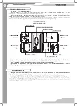
UNIT CONTROL
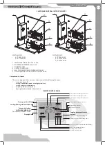
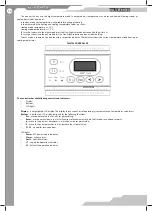
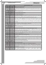
General description of the automation control system.
The unit is equipped with a built-in electronic control and automation unit and a remote control panel.
The automatic control system has the following functions:
1.
Switching the unit ON/OFF;
2.
Maintenance of set supply temperature by means of automatic regulation of the electric heating coil capacity;
3.
Electric heater overheating protection with two thermostats;
4.
Rotary heat exchanger control;
5.
Supply and exhaust fans control and monitoring;
6.
Supply and exhaust air controlling damper actuating;
7.
System shutdown on signal from fi re fi ghting system.
The controller has the following functions: electric heater and rotary heat exchanger control, air damper opening and closing.
The supply air temperature is maintained at set point during the fan operation by means of electric heater power regulation
performed by triac units. In case of the unit shutdown the automatic control system provides air supply to the electric heating elements
within n minutes (adjustable parameter E-01) for heat removing.
The automatic control system provides automatic restart of the fans after power failure. This function is activated and adjusted from
the controller menu.
Design.
Name
Type
Cable**
SM1
Supply air damper actuator
LF230
2x0.75 mm
2
SM2
Extract air damper actuator
LF230
2x0.75 mm
2
PK1
Contact from fi re alarm panel
NO
2x0.75 mm
2
P1
Remote control panel
SAS908PIT
TE1
Intake air temperature sensor
PT-1000 ST-01
2x0.75 mm
2
CCB
DX-cooler
4x0.75 mm
2
1. The unit comprises P1 and TE1 only.
2. ** - Max. connecting cable length is 20 m!
3. Cable length from P1 must not exceed 10 meters.
Содержание VUT R 1200 EH EC
Страница 22: ...2013 V76EN 02 ...


