background image

22

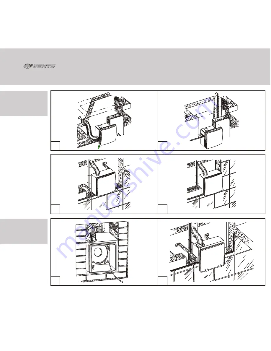
INSTALLATION 

EXAMPLES

VNV-1 80 KV,

VNV-1 80 KVK

19

20

17

18

INSTALLATION 

EXAMPLES

VNV-1 80 KP

21

22

VN

VN

Содержание KP 80

Страница 1: ...Operation Manual 2012 VN VN ...

Страница 2: ...ons Manufacturer s warranty Figures external view and dimensions Figures installation options Figures fan mounting options relative to walls and ceiling Figures installation sequence Figures power mains connection Schematic diagrams of fan connection to power mains Figures timer and humidity sensor setup Acceptance certificate Warranty card ð 3 ð 4 ð 5 ð 6 ð 6 ð 7 ð 7 ð 9 ð 12 ð 13 ð 13 ð 13 ð 16 ...

Страница 3: ...s with reduced physical mental or sensory capacities lacking practical experience or knowledge unless not controlled or briefed on the device operation by the person responsible for their safety Children must remain under the supervision of adults who must prevent their playing with the device Take all the reasonable steps to prevent penetration of smoke carbon monoxide and other combustion produc...

Страница 4: ... designation 3 VN 1 A 80 H High Pressure Fan with a plastic front panel air flow rate 35 60 m h outlet diameter 80 mm equipped with a humidity sensor Casing Type Unmarked external plastic casing K external plastic casing with a fire damper KV in the wall plastic casing KP in the wall fire preventing casing KVK in the wall plastic casing with a fire damper XXX D with a supplementary bottom spigot X...

Страница 5: ...he wall fire preventing casing KVK in the wall plastic casing with a fire damper DELIVERY PACKAGE VN 80 Ê VN 1 80 Ê VNV 1 80 ÊV 80 ÊP 80 KVK 80 Fan System complete pcs Fan Assembly pcs Casing pcs Set of Fasteners pcs Mounting Bracket pcs Protective fiberboard plate pcs Plastic screwdriver pcs only for timer equipped models Operation Manual pcs Packing Box pcs 1 1 1 1 1 1 1 1 1 1 1 1 1 1 1 1 1 1 VN...

Страница 6: ...NTS VN 80 Ê models comply with special fire safety requirements and are designed to protect the premises against smoke fumes which may penetrate through the air ducts in case of a fire The figures 1 through 11 show the outside and connection dimensions of the products The main parameters are given in Table 1 MAIN TECHNICAL SPECIFICATIONS Table 1 Basic Model 220 240 17 27 48 0 14 0 18 0 21 63 102 1...

Страница 7: ...onstantly operates at speed 1 When turned on with an external switch the fan switches to speed 2 after 50 second delay Following turning off the fan continues running at speed 2 for 6 minutes and then reverts to the initial state automatically TR with an adjustable timer Depending on the connection pattern the fan remains off or constantly operates at speed 1 Following activation with an external ...

Страница 8: ...operates at speed 1 The fan switches to speed 2 on with an increase of relative humidity level on the premises The sensor operating threshold can be set from 60 to 90 The unit switches off on relative humidity dropping 10 below the pre set level The fan can be manually set to speed 2 on light switch actuation In this case the actuation delay is 50 seconds whereas the operating interval is controll...

Страница 9: ... the dowels Fig 33 1 7 Install the fan casing and scroll assembly and secure it with self tapping screws Fig 34 1 8 Perform operations 1 2 1 4 in the reverse order To install VN 80 fan 2 1 Mark and drill a hole for the outlet fitting following one of the 4 installation options Fig 25 28 2 2 Remove the decorative blind Fig 35 2 3 Remove the front panel retention screw Fig 36 2 4 Remove the front pa...

Страница 10: ...ns are installed in two stages i e the casing installation is followed by the final assembly The casing is installed at the structural works stage The final assembly follows the interior finishing and includes installation of VN 1 80 fan assembly into KV 80 KK 80 or KP 80 casing To install KV 80 and KK 80 casing 5 1 Perform operations 1 2 1 4 5 2 Remove the fan assembly from the casing Fig 48 49 5...

Страница 11: ... installed inside a wall or in the counterceiling recess using mounting brackets Fig 22 6 6 Following the installation cover the casing with the protective fiberboard plate to prevent damage or accumulation of dirt on the casing during the interior finishing of premises Fig 54 To perform final assembly of VNV 1 80 KV VNV 1 80 KVK and VNV 1 80 KP fans 7 1 On completion of interior finishing remove ...

Страница 12: ...or to mounting the fan check the position of back valve 2 which should close under its own weight at zero air pressure Fig 63 By default the back valve position matches the outlet fitting orientation to the right or upwards If the outlet fitting is faced left during the fan installation remove the back valve from fitting 1 rotate the valve 180 and reinstall it into the fitting For modular air duct...

Страница 13: ... latches and remove the scroll Fig 73 Rotate the scroll 180 to access the turbine and remove the dust using a soft brush or compressed air stream Fig 74 Re assemble the fan in the reverse order and connect it to the power mains Fig 75 The unit can be carried in the original packing by any mode of transport without limitation The unit must be stored in the original packing at ambient air temperatur...

Страница 14: ... with the one stated in the User s Operation Manual or its substitute To benefit from warranty service please contact your retailer If the warranty service may not be provided at the office you have contacted you will be referred to an alternative provider The manufacturer s warranty does not apply in the following cases Customer s failure to submit the product complete with all the parts and acce...

Страница 15: ...sing payment document certifying the purchase with a statement of purchase date The Manufacturer shall be liable only for the defects which have arisen through its fault prior to product delivery to the user However the Manufacturer shall not be liable for any defects which have arisen following the product delivery to the user and have resulted from violation of product transportation storage ins...

Страница 16: ...16 2 1 235 215 VN 80 235 215 199 135 79 102 244 244 203 138 79 102 VN 1 80 VN VN ...

Страница 17: ...17 4 3 VN 80 Ê 244 215 80 75 138 204 215 244 135 201 80 75 235 235 VN 1 80 Ê VN VN ...

Страница 18: ...18 271 109 102 80 156 265 320 56 VNV 1 80 KP VNV 1 80 KV 235 215 90 102 138 244 79 65 304 6 5 VN VN ...

Страница 19: ...19 VNV 1 80 VNV 1 80 KVK 265 67 135 102 80 75 215 320 235 8 7 VN VN ...

Страница 20: ...20 KV 80 KP 80 KVK 80 10 9 11 VN VN ...

Страница 21: ...21 INSTALLATION EXAMPLES VN 80 VN 1 80 VN 80 Ê VN 1 80 Ê 12 13 14 15 16 VN VN ...

Страница 22: ...22 INSTALLATION EXAMPLES VNV 1 80 KV VNV 1 80 KVK 19 20 17 18 INSTALLATION EXAMPLES VNV 1 80 KP 21 22 VN VN ...

Страница 23: ...TH SUPPLEMENTARY INLET FITTING VN 80 VN 1 80 VN 80 VN 1 80 VN 80 Ê VN 1 80 Ê VN 80 VN 1 80 VN 80 Ê VN 1 80 Ê 75 75 25 27 26 28 75 275 75 75 275 75 90 90 90 90 VN 80 VN 1 80 VN 80 Ê VN 1 80 Ê FAN MOUNTING EXAMPLES RELATIVE TO WALLS AND CEILING VN VN ...

Страница 24: ...30 29 VN 1 80 INSTALLATION PROCEDURE 24 31 32 33 34 VN VN ...

Страница 25: ...VN 80 INSTALLATION PROCEDURE 35 36 25 37 VN 1 80 K INSTALLATION PROCEDURE 38 39 VN VN ...

Страница 26: ...40 41 26 42 43 44 VN VN ...

Страница 27: ...27 VNV 1 80 KV VNV 1 80 KVK VNV 1 80 KP INSTALLATION PROCEDURE 45 46 47 48 49 VN VN ...

Страница 28: ...28 PROTECTIVE FIBERBOARD PLATE 50 51 52 53 54 55 VN VN ...

Страница 29: ...29 60 61 62 5 2 0 64 ELECTRICAL MAINS CONNECTION 63 1 2 VN VN ...

Страница 30: ...h P3 1 300 shown schematically The fan is set to one of the three speeds as necessary or switched off manually with the help of external switch S e g P3 1 300 The fan is set to one of the 3 speeds with the help of the external switch S e g P3 1 300 The fan is activated or deactivated simultaneously with the light in the premises The fan is activated deactivated only simultaneously with the lights ...

Страница 31: ... N 1 A S 2 2 EL 1 N S 2 OFF 2 L N OFF 1 A S SW The fan is set to one of the 2 speeds as required with the help of external switch S e g P2 1 300 or switched off The fan is set to one of the 2 speeds with the help of external switch S e g P2 1 300 The fan is activated or deactivated simultaneously with the lights on the premises The fan is activated deactivated only simultaneously with the lights O...

Страница 32: ... modifications A B and D CONTINUED 67 B A A Fan B Distribution box SW two position switch shown schematically SW The fan constantly remains on operating at speed 1 or speed 2 The speed is selected with the help of switch SW L N A 1 N SW 2 32 VN VN Diagram 5 ...

Страница 33: ...o 150 seconds option TR On opening switch S1 the illumination on the premises is switched off whereas the fan continues to operate according to the timer setting for 6 minutes T or for an interval from 2 to 30 minutes TR and then automatically switches to speed 1 or switches off With interval switch I The fan equipped with an interval switch I constantly operates at speed 1 with switch SB closed o...

Страница 34: ...imer On switching the lights off the fan continues to operate until elapsing of the timer setting which may range from 2 to 30 minutes and then switches off automatically speed 1 is not used in this operation pattern The fan constantly operates at speed 1 with switch SB closed or remains off with the switch open On switching the lights on the photoelectric sensor sets the fan to speed 2 on elapsin...

Страница 35: ...relative humidity on the premises increases the fan automatically switches to speed 2 and maintains it until humidity drops to the pre set level The fan constantly operates at speed 1 As the relative humidity on the premises increases the fan automatically switches to speed 2 and maintains it until humidity drops to the pre set level You may use switch S1 which also doubles as the light switch to ...

Страница 36: ...utomatically switches to speed 2 and maintains it until humidity drops to the pre set level irrespective of switch S1 position The fan initial state is off As the relative humidity on the premises increases the fan automatically switches to speed 2 and maintains it until humidity drops to the pre set level You may use switch S1 which also doubles as the light switch to manually engage speed 2 In t...

Страница 37: ...37 72 73 74 FAN MAINTENANCE 75 VN VN ...

Страница 38: ...es Modification I Fig 77 Ò interval timer can be set within the range from 30 minutes to 15 hours Modification F Fig 77 Ò turn off delay can be set from 2 to 30 minutes Modification H Fig 78 Ò turn off delay can be set from 2 to 30 minutes H humidity sensor threshold can be set within the range from 60 to 90 TIMER AND HUMIDITY SENSOR ADJUSTMENT VN VN ...

Страница 39: ...hop stamp Sale Date We hereby declare that the following product complies with the essential protection requirements of Electromagnetic Council Directive 2004 108 EC 89 336 EEC and Low Voltage Directive 2006 95 EC 73 23 EEC and CE marking Directive 93 68 EEC on the approximation of the laws of the Member States relating to electromagnetic compatibility This certificate is issued following test car...

Страница 40: ...WARRANTY CARD V22EN 06 40 VN VN ...

Отзывы: