background image

5

www.ventilation-system.com

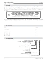
The unit is designed for indoor application with the ambient temperature ranging from +1 °C up to +40 °C and relative humidity up to 80 %.
The unit is rated as a Class I electrical appliance.
Hazardous parts access and water ingress protection rating:
•  IP22 for the assembled unit connected to the air ducts
•  IP44 for the unit motors
The unit design is constantly being improved, thus some models may be slightly different from those described in this manual.

PARAMETER

D

VUT 300 P(1)B EC


VUT 300 P(1)BE EC

D

VUT 300 P(1)BE2 EC

D

VUT 500 P(1)B EC

D

VUT 500 P(1)BE EC

D

VUT 500 P(1)BE2 EC

Power supply voltage, 50 (60) Hz [V]

1~ 220-240

Unit power consumption excl. electric heater [W] 

175

230

Pre-heater power consumption [W]

-

1050

-

1050

Re-heater power consumption [W]

-

-

1400

-

-

1400

Maximum unit current excl. electric heater [A]

1.3

1.7

Maximum unit current incl. electric heater [A] 

-

7.3

13.6

-

7.2

13.5

Max. air capacity [m

3

/h] 

300

510

RPM [min-1]

2150

1700

Noise level, 3 m [dBA] 

22

24

Transported air temperature [˚C]

-25 up to +50

Casing material

painted steel

Insulation

40 mm, mineral wool 

Extract air filter

G4

Supply air filter

G4, F8 (optional: F8 + Carbon; H11)

Connected duct diameter [mm]

200

250

Weight [kg]

78

79

80

103

104

105

Heat recovery efficiency [%]

79 up to 91

79 up to 94

Heat exchanger type

counter-flow

Heat exchanger material

aluminium

SEC class

A

TECHNICAL DATA

Содержание DVUT 300 P1B EC

Страница 1: ...USER S MANUAL Single room heat recovery air handling unit DVUT 300 PB EC A17 18 DVUT 300 PBE EC A17 18 DVUT 300 PBE2 EC A17 18 DVUT 500 PB EC A17 18 DVUT 500 PBE EC A17 18 DVUT 500 PBE2 EC A17 18 ...

Страница 2: ...reproduced stored in a retrieval system or transmitted in any form or by any means in any information search system or translated into any language in any form without the prior written permission of the Company Please read the user s manual carefully prior to installing and operating the unit All user s manual requirements as well as the provisions of all the applicable local and national constru...

Страница 3: ...er mains prior to any technical maintenance Do not store any explosive or highly flammable substances in close proximity to the unit When the unit generates unusual sounds odour or emits smoke disconnect it from power supply and contact the Seller Do not open the unit during operation Do not direct the air flow produced by the unit towards open flame or ignition sources Do not block the air duct w...

Страница 4: ...t part and is not designed for stand alone operation The unit is designed to ensure continuous mechanical air exchange in houses offices hotels cafés conference halls and other utility and public spaces as well as to recover the heat energy contained in the air extracted from the premises to warm up the filtered stream of supply air The unit is rated for continuous operation Transported air must n...

Страница 5: ... BE EC DVUT 500 P 1 BE2 EC Power supply voltage 50 60 Hz V 1 220 240 Unit power consumption excl electric heater W 175 230 Pre heater power consumption W 1050 1050 Re heater power consumption W 1400 1400 Maximum unit current excl electric heater A 1 3 1 7 Maximum unit current incl electric heater A 7 3 13 6 7 2 13 5 Max air capacity m3 h 300 510 RPM min 1 2150 1700 Noise level 3 m dBA 22 24 Transp...

Страница 6: ...00 PBE EC DVUT 300 PBE2 EC DVUT 300 P1B EC 1100 1101 399 DVUT 300 P1BE EC DVUT 300 P1BE2 EC DVUT 500 PB EC 249 1806 1316 244 1018 1083 386 400 169 217 DVUT 500 PBE EC DVUT 500 PBE2 EC DVUT 500 P1B EC 1314 1349 386 462 DVUT 500 P1BE EC DVUT 500 P1BE2 EC UNIT WITH HORIZONTAL SPIGOTS B H H1 A B1 A2 A2 A1 H2 H3 D UNIT WITH VERTICAL SPIGOTS D B A A1 H H1 ...

Страница 7: ...th locks provides convenient service access for maintenance of the unit The heat exchanger freeze protection mode is activated automatically on temperature sensor feedback as follows Automatic shut down of the supply fan Bypass air duct with bypass damper The bypass damper closes the bypass air duct to direct the supply air flow bypassing the heat exchanger Automatic turning the pre heater on A fr...

Страница 8: ...et point the unit reverts to the previous operation mode ATTENTION Selectaprioritysensorinthecontrolpaneltocontroloperationoftheairhandlingunitasdescribedinthesection Unit control panels clause Air quality Warm extract air from the room flows into the unit and is cleaned in the extract filter Then the air is moved through the heat exchanger and is exhausted outside with the extract fan Cold fresh ...

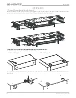
Страница 9: ...m Screw Bracket Washer Expansion anchor Vibration absorbing rubber To attain the best performance of the unit and to minimise turbulence induced air pressure losses connect straight air duct sections to the unit spigots The minimum straight air duct length is equal to 1 air duct diameter on intake side and 3 air duct diameters on outlet side If the air ducts are too short or not connected protect ...

Страница 10: ...on the mounting bracket and the four L brackets Take off the mounting bracket and the L brackets 2 Make recesses in the wall and ceiling depending on the unit installation type Mark the fastening holes using the template for installation of the unit With horizontal spigots With vertical spigots Using the marking drill the holes and through holes in the wall for the air ducts with the diameter 220 ...

Страница 11: ...allation in the wall and after completion of mounting In the first case the required air duct length must be calculated prior to installation and in the second case sufficient access to the outer wall must be provided for adjustment of the air duct length after it is installed and fixed min 3 mm 4 Mounting options Using the mounting bracket Install the bracket in the wall ceiling corner lign the a...

Страница 12: ...x the outer ventilation grilles on the outer wall The grilles are not included in the delivery set and are available as specially ordered accessories 7 Mounting of the unit with vertical spigots Install the bracket in the wall ceiling corner Attach the L brackets to the ceiling Align the air ducts with the unit spigots and fix the unit on the bracket and L brackets Connect the decorative panel and...

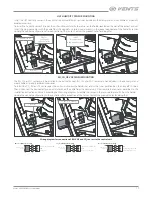
Страница 13: ...he delivery set and are available as specially ordered accessories To install the CO2 RH or VOC sensor open the unit and unscrew the holder that retains the inner partition box then take off this box Then disconnect the connector pre wired at works on the cable from the control unit Disassemble the sensor as described in the installation instruction and wire it according to the wiring diagram Asse...

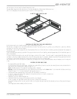
Страница 14: ...the sewage system Condensate drain pipe Ø 16x2 mm U trap hydraulic lock Sewage system min 100 mm min 50 mm min 3 ATTENTION Keep the minimum slope of 3 while mounting the pipes to provide correct water drainage Before starting operation of the unit make sure that the water flows freely into the sewage collection system otherwise condensed water may build up in the unit during the heat exchanger ope...

Страница 15: ...he telephone cable to the installation place of the control panel Fix the back side of the casing in a standard junction box using the supplied round head screws 2 Connect the telephone cable to the front side of the control panel Fix the front part of the control panel to its back part using the supplied countersunk head screws as shown below Then press the front frame to click to install it The ...

Страница 16: ...ront side of the control panel 3 Complete wiring in compliance with the wiring diagram 4 Fasten the back side of the control panel in the junction box using the supplied screws 5 Re attach the four pin socket Press the control panel to click 6 Lay all the wires inside of the control panel and install the control panel from below Press the panel to click and close 4 5 6 4 5 6 74 60 74 60 Overall di...

Страница 17: ...ply and extract fan is set for each speed stage individually as a percentage ratio of the maximum rotation speed The temperature is set with the Temp Set parameter Operation of the unit may be programmed using a scheduler max 4 time bands a day CONTROL SYSTEM FUNCTIONS Turning on of the operation modes Auto automatic heater operation mode Automatic activation of the re heater is only then enabled ...

Страница 18: ...centration exceeds the set point option OPERATION OF THE UNIT WITH THE PGD1 CONTROL PANEL The graphic PGD1 control panel has expanded functionality and duplicates the settings set on the controller display see Controller functions and menu Connect the pGD1 control panel to the controller connector using the 6P6C PLUG 6P6C P C2 phone plug The maximum telephone cable length is 50 m CONTROLLER FUNCTI...

Страница 19: ... ESC PUSH The rotary knob is used to set the parameters For accessing parameters of the humidity sensor or CO2 sensor applicable for some air handling units models press the rotary knob th Tune 1 3 2 19 18 11 12 13 14 15 16 17 4 6 5 7 8 9 10 Display symbols 1 Heating mode operation No indication VENT mode air re heating in ventilation mode is disabled auto mode is activated air re heating dependin...

Страница 20: ...ce or clean the filters In this case clean or replace the filters and reset the filter timer Filter cleaning with a vacuum cleaner is allowed After two consecutive cleanings the filters must be replaced For new filters of the type stated in the technical data please contact to the unit Seller Steps for removal of the filters 1 Disconnect the unit from power supply 2 Open the service door using the...

Страница 21: ...er 3 Fan maintenance once a year Even in case of regular maintenance of the filters some dust may accumulate inside the fans and reduce the fan performance and supply air flow Clean the fans with a soft cloth brush or compressed air Do not use water aggressive solvents or sharp objects as they may damage the impeller 4 Maintenance of air intake devices twice per year The supply grille may get clog...

Страница 22: ...ged extract filter Clean or replace the extract filter Contaminated heat exchanger Clean the heat exchanger Noise vibration Clogged impeller or impellers Clean the impeller or impellers Loose screw connection in the fan or in the casing Tighten the screws of the fans or the casing against stop Noanti vibrationconnectorsontheconnection spigots Install the rubber anti vibration connectors Store the ...

Страница 23: ...he user s manual with the purchase date stamp and the payment paperwork certifying the purchase The unit model must comply with the one stated in the user s manual Contact the Seller for warranty service The manufacturer s warranty does not apply to the following cases User s failure to submit the unit with the entire delivery package as stated in the user s manual including submission with missin...

Страница 24: ... unit delivery with the user s manual The warranty terms are acknowledged and accepted Customer s Signature The DVUT _________ P_B ______ EC A ______ unit has been connected to power mains pursuant to the requirements stated in the present user s manual Installation Company Stamp Seller Address Phone Number Installation Technician s Full Name Installation Date Signature The unit has been installed...

Страница 25: ...25 www ventilation system com ...

Страница 26: ...26 DVUT PB EC www ventilation system com ...

Страница 27: ...27 www ventilation system com ...

Страница 28: ...V177EN 01 ...

Отзывы: