GENERAL OPERATION
Operation - 26
T
URNING
R
ADIUS
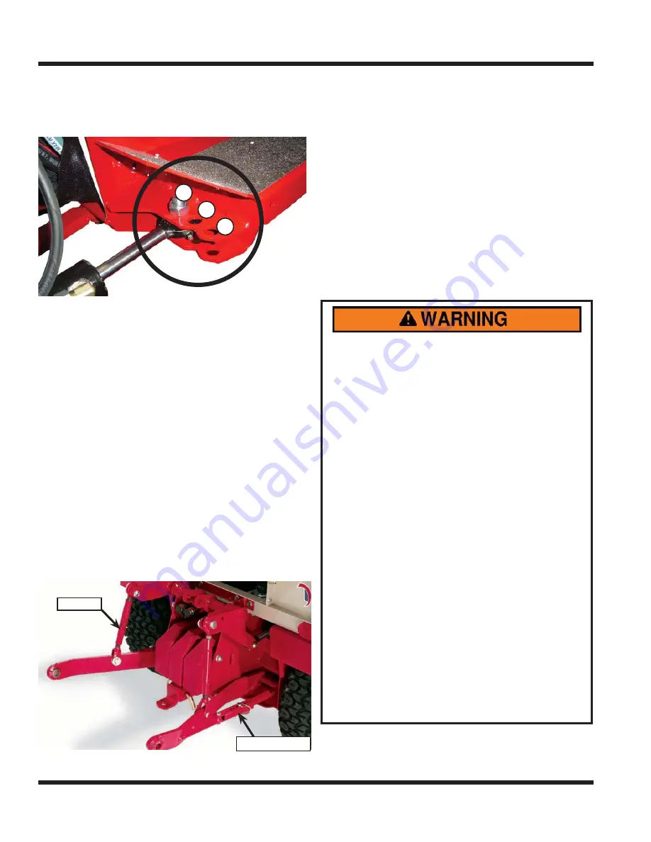
Your power unit has three mounting positions for
the steering cylinder that determine the power unit’s
turning radius.
1
1
2
2
3
3
Position
#
1: Standard position. This position is the stan-
dard position, and enables the tightest turning radius.
Position
#
2: Dual wheel position. The steering cylin-
der must be installed in this position when operating
with dual wheels. The resulting turning radius will be
larger than in position
#
1.
Position
#
3: Cab and Versa-loader position. The
steering cylinder must be installed in this position
when the cab is installed or when operating the
Versa-loader. The resulting turning radius will be
larger than in position
#
2.
3 P
OINT
H
ITCH
(O
PTIONAL
A
CCESSORY
)
Some light and medium duty implements (non-PTO
powered) can be used on the rear of a 3 point hitch
equipped power unit.
The 3 point hitch is equipped with adjustable lift links
to control the individual draw bars. The stabilizing
links can be allowed to swing freely or can be locked
at a desired position.
Lift Link
Stabilizing Link
Stabilizing Link
The 3 point hitch is equipped with three control
handles. The inside handle raises and lowers the
draw bar. The middle handle controls the left rear set
of hydraulic quick couplers. The outside handle con-
trols the right rear set of hydraulic quick couplers.
12 V
OLT
A
UXILIARY
O
UTLETS
(O
PTIONAL
A
CCESSORY
)
Certain attachments require a 12 volt auxiliary out-
let. Plug the attachment’s 12 volt power cord into the
12 volt 4-pin plug located above the front auxiliary
quick couplers. Two switches are used to control
the actions of the 12 volt kit. A momentary on/off/on
is used for controlling movement that is only used
for a brief time. The on/off switch is used to activate
equipment or select different functions.
O
PERATING
O
N
S
LOPES
AVOID PERSONAL INJURY!
Operation on slopes decreases power unit stabil-
ity and increases the potential for unexpected
dif
fi
culties. Only experienced operators should
operate the power unit on slopes and extra cau-
tion should be exercised.
• Use low range when operating on slopes
greater than 15 degrees.
• Never shift between high and low range while
on a slope. Always move the machine to level
ground and place the selector lever in park
before shifting range.
• Avoid uneven, loose, or wet terrain.
• Stay clear of drop-offs, holes, ditches, rocks,
or objects that could cause a sudden and/or
unexpected force on the power unit.
• Make slow and cautious starts, stops, and turns.
• Do not exceed the maximum degree of
operation. Refer to illustrations.
• Turn downhill when possible and/or reduce
the degree of turns.
• Assure a suf
fi
cient supply of fuel for continu-
ous operation. A minimum of one-half tank of
fuel is recommended.
• To prevent fuel spillage, do not remove the
fuel tank cap while power unit is on a slope.
• Failure to follow items listed or to use com-
mon sense while operating on slopes can
result in injury or death. Always operate on
slopes with caution.
GENERAL OPERATION


