background image

Product Description 

Kinetic MVHR Installation & Commissioning 

4


Kinetic Plus E 

The Vent-Axia

 Kinetic Plus E Mechanical Ventilation/Heat Recovery (MVHR)

 is heat recovery unit designed 

for the energy efficient ventilation of houses and similar dwellings, conforming to the latest requirements of the 
Building Regulations document F 2010.  

The unit is designed for continuous 24 hour exhaust ventilation of stale moist air from bathrooms, toilets and 
kitchens. As the stale air is extracted, a heat exchanger within the unit transfers up to 94% of the heat and 
transfers it into the supply air entering the bedrooms and lounge.  


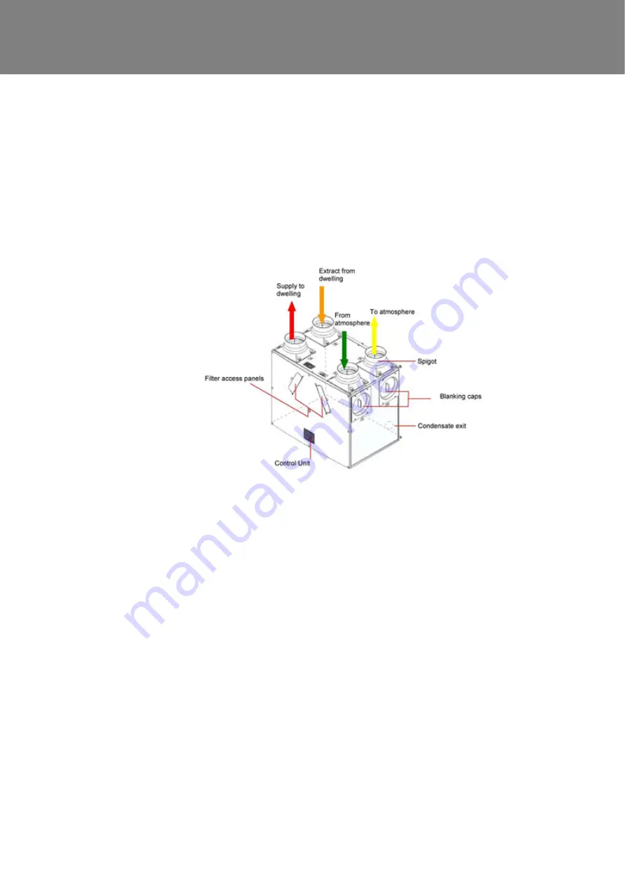
Figure 1: Kinetic Plus E (Front of Unit as supplied) 


A wide range of sensors is available that can be used to switch Kinetic Plus E from normal to boost speed and 
they are: 


 TimeSpan 

 Air 

Quality 

Sensor 


Ambient Response Humidity 

 Vent-Axia 

HumidiSwitch 

 Vent-Axia 

ThermoSwitch 


Normal Boost Switch 

 Vent 

Wise


Содержание Kinetic Plus E

Страница 1: ...Copyright 2009 Vent Axia Limited All rights reserved Kinetic Kinetic Plus E MVHR Installation Commissioning Stock Ref N 449059 Kinetic Plus E PLEASE RETAIN THESE INSTRUCTIONS WITH THE PRODUCT...

Страница 2: ...ildren should be supervised to ensure that they do not play with the appliance INSTALLATION GUIDANCE 1 The installer is responsible for the installation and electrical connection of the sentinel syste...

Страница 3: ...Up the Unit 18 Commissioning Overview 19 Commissioning Control 20 Maintenance Filter Maintenance 22 12 Monthly Maintenance 22 Spares 23 Product Fiche 24 UK Building Regulations Part F Declaration of C...

Страница 4: ...ontinuous 24 hour exhaust ventilation of stale moist air from bathrooms toilets and kitchens As the stale air is extracted a heat exchanger within the unit transfers up to 94 of the heat and transfers...

Страница 5: ...uency Input 50 Hz nominal Rated Power 190 W max Physical Height excluding spigots 630 mm Width excluding spigots 775 mm Depth 524 including filter flap hinge protrusion Weight 24 kg Spigot diameter 15...

Страница 6: ...c MVHR Installation Commissioning 6 Figure 2 Kinetic Plus E Dimensions KINETIC Plus E Performance graph for Vertical and Horizontal Discharge Note Graph show 2 typical system curves with total unit in...

Страница 7: ...fety Information on page 2 Unit Installation The Kinetic Plus E unit is typically installed on a wall in a utility room storage cupboard roof void or similar The wall should have sufficient strength t...

Страница 8: ...ough 180 degrees and then re attaching them This moves the condensate drain exit from the right rear corner of the unit to the left front corner of the unit when viewed from the front viewing the Cont...

Страница 9: ...e required ensure that you use a grommet or gland to protect against potential water ingress 7 Re attach the Cable Inlet Plate on the opposite side of the unit 8 Fit the Control Panel on the opposite...

Страница 10: ...the unit 2 Remove the black Cap from the end of the condensate stub at the rear of the unit 3 Fit the vertical condensate pipe and secure with worm drive clip The condensate pipe can be attached with...

Страница 11: ...ischarge remove the front cover and locate the condensate stub at the front of the unit 2 Remove the Black Cap from end of condensate stub at the front of the unit 3 On the Kinetic Plus E drill a diam...

Страница 12: ...ipe fitted with 22 32mm reducer Fit a U bend condensate drain having a minimum of a 60mm water seal or a HepvO valve to the building s foul water drainage system and ensure there is a minimum 3 degree...

Страница 13: ...d with either diameter 180 mm ducting or diameter 200 mm ducting These foam adaptors are to be fixed to the outside of the spigot for diameter 200 mm ducting To move the spigots 1 Remove the spigot by...

Страница 14: ...cket positions using the template below A paper copy can be obtained from Vent Axia Technical Support 4 Fit metal wall brackets supplied to the wall using appropriate fixings 5 Fit the stand off feet...

Страница 15: ...short piece of flexible duct 100 150 mm long extended to its full length when connecting to ductwork 2 Securely connect this ducting to the spigots using worm drive clips or cable ties 3 Insulate any...

Страница 16: ...button on the control unit may be used Table 1 Mains Cable Connections Terminal No Name Cable connection Description L Mains Live Brown 220 240 V AC 50 Hz input N Mains Neutral Blue 220 240 V AC 50 Hz...

Страница 17: ...off 2 One end of the power cable supplied is already connected to the unit and routed through the Cable Inlet Plate via a suitable gland to ensure the IP rating of the unit is not affected 3 Connect...

Страница 18: ...tallation Commissioning 18 Powering Up the Unit Switching On Switch on the power at the mains supply isolator feeding the unit and the fan motors will start Switching Off Turn the power off at the mai...

Страница 19: ...hen commissioning the unit Ensure that the system is installed according to the system designers intent incorporating any acoustic ducting that all joints are air tight ducting is well supported bends...

Страница 20: ...potentiometers to suit Figure 3 KINETIC PLUS E Controls Summer Mode The unit is equipped with a Summer Mode for use when the indoor temperature is higher than desired and the outdoor temperature is l...

Страница 21: ...s once to activate Boost mode Press once again to exit Boost mode To activate Summer Mode press 3 times in less than three seconds after a short pause the green LED will illuminate and the supply fan...

Страница 22: ...or 10 seconds Periodic Maintenance Item Action Fan Filters Change the Fan Filters 1 Open the filter flaps and remove the 2 filters 2 Insert the replacement filters 3 Close the filter flaps 4 Reset the...

Страница 23: ...The following spares may be ordered from Vent Axia Kinetic Plus E Spares Part No Description 403732 Control Board 404943 T1 Temperature Sensor 403702 Filters 2 per pack 403733 Heat Recovery Cell 40335...

Страница 24: ...iff Pa 350 SPI W m3 h 0 28 Control Factor Control Typology CTRL Typology Control Factor CTRL 0 65 Control Typology Local Demand Control Declared Max Internal External Leakage Rates for BVUs or carry o...

Страница 25: ...t being found to be defective the product will be repaired or at the Company s option replaced without charge provided that the product Has been installed and used in accordance with the instructions...

Отзывы: