


26
10.0 Changing Components
IMPORTANT: ISOLATE FROM THE
ELECTRICAL SUPPLY BEFORE STARTING
ANY WORK ON THE APPLIANCE.
The fans continue to rotate for one minute after
isolating from the electrical supply
10.1
Controller
1. HR205 Only - Fully extend the telescopic
cooker hood and remove the two metal filters.
2. Remove the outer door by releasing the two
screws and lifting the door up and forwards.
3. Remove the bottom electrical cover by
releasing the 3 screws, pulling the panel
forwards and disconnecting the earth lead to the
panel. Make a note of the voltage setting for the
fans and of the wiring arrangement for the
controller.
4. Release all the wires connected to the
controller.
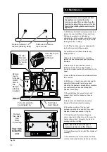
5. Remove R.H. fan cover panel and remove the
R.H. fan (see Section 10.3). Unscrew the two
screws securing the controller mounting bracket
to the bulkhead and remove the bracket and
controller unit. Separate the bracket from
controller by removing the four screws.
6. Re-assemble with the new controller in
reverse order. Check the electrical installation
for; Earth continuity, short circuits,
resistance to earth and correct polarity.
10.2
Overheat thermostat - HR205 Only
1. Lift off the front door panel by releasing the
two hand screws and lifting upwards.
2. Remove the bottom electrical cover by
releasing the 3 screws, pulling the panel
forwards and disconnecting the earth lead to the
panel. Identify the connections for the overheat
thermostat. Make a note of the routing for the
overheat thermostat cable.
3. Release the overheat thermostat connections.
4. Release the sensor head by springing open
the clip and pulling out the sensor head.
5. Remove the overheat thermostat taking care
not to dislodge the bulkhead grommet.
6. Carefully locate the new sensor and position
the lead as shown in Fig. 26. Re-assemble with
the new overheat thermostat in reverse order.
Check the electrical installation for; Earth
continuity, short circuits, resistance to earth
and correct polarity.
WHC0018A
Warning
FRONT
UP
Rear View of the Controller
Controller
Mounting
Bracket
Mounting
bracket to
bulkhead
securing
screws (2 off)
Controller
securing
screws (4 off)
Controller
Bulkhead
L
N
160
140
120
100
80
Take note of the fan speed setting,
120v shown. When the new controller
is fitted, fit the white lead to the
position of the old controller for the
correct fan speed.
Controller
Remove RH fan cover
panel & bottom cover panel.
Overheat
Thermostat
Head
Overheat
Thermostat
Sleeve
Cable
Tie
Overheat
Thermostat
Clip
Bulkhead
Grommet
HR205
Fig. 25
Содержание HR205
Страница 29: ...29 This page is intentionally blank...
Страница 36: ...372705C 0208...