


14
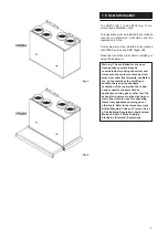
Exh
aus
t
Ou
t
Fres
h A
ir
In
Ho
t St
ale
Air
In
Wa
rm
Air
Ou
t
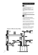
Measure 700mm
from hob
HR205
HR204
Top of hob
Example of a possible
understairs installation
Mark out the
position of the
unit of the
Wall Template
Ground Floor
Stair Case
Make sure the Wall
Template is level
Mark position
of the
condensate
pipe 15 mm
(drill where
required)
Mark position
of the
fixing holes
2 top (minimum)
& 1 lower
then drill & plug
WHC0013A
Wall Template
HR204 &
HR205
(with cooker hood)
Whole House Ventilation System
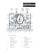
Exhaust
Out
Fresh Air
In
Hot Stale
Air In
Warm Air
Out
Minimum
Top
Clearance
200mm
Part No. 372706
98mm
Cooker Hood
Bottom of
MVHR Unit
Bottom of
Cooker Hood
Top of
MVHR
Unit
Bottom of
Mounting
Brackets
4 Fixing Holes
(Key Holes)
Use one
hole each side
Bottom
Fixing Hole
Back Case
Condensate Hole
Side Case Knock
Out Condensate Hole
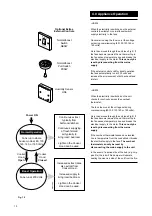
Minimum Side
Clearance 1mm
Minimum Side
Clearance 1mm
Bottom Condensate
Pipe Exit (HR204 Only)
Minimum Bottom Clearance
100mm
(HR204 Model)
Minimum Side
Clearance
24mm
(HR205c)
Minimum Side
Clearance
5mm
(HR204)
MVHR
Side
Minimum Side
Clearance
24mm
(HR205c)
Minimum Side
Clearance
5mm
(HR204)
MVHR
Side
All dimensions
in mm
Minimum Top
Clearance
for servicing
200
Minimum
Side
Clearance
5
Minimum
Side
Clearance
5
Clearances
HR204
Minimum Bottom
Clearance
100
Minimum
Front
Clearance
for
servicing
250
280
Clearances
HR205c
Minimum
Side
Clearance
(MVHR)
24
Minimum
Side
Clearance
(MVHR)
24
Minimum
Top Clearance
for servicing
200
300
Minimum
Front
Clearance
for servicing
250
Minimum Bottom
Clearance from Hob
700
Minimum
Side
Clearance
(C.Hood)
1
Measure Minimum
Bottom Clearance
700mm
From Hob
(HR205c Model)
Mains
Cable
Outlet
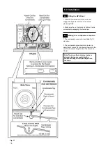
6.0 Installation
6.1
Preparation
1. Check site requirements (Section 5) before
commencing.
2. Remove the fixing template from the MVHR
carton.
After considering the site requirements position
the template on the wall ensuring it is level.
3. Mark the positions of at least two top fixing
holes, the lower fixing hole and the condensate
outlet.
If required mark off the positions of the four duct
connections.
4. Drill and plug the wall at the fixing points
and drill the condensate hole.
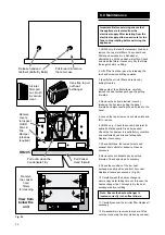
5. The top two screws should now be fitted
leaving enough space for the keyhole fixing slots
to engage.
6. Place the MVHR unit on its back (Fig. 15). Lift
off the front door panel by releasing the two
hand screws and lifting upwards.
7. Remove the bottom electrical cover by
releasing the 3 screws, pulling the panel
forwards and disconnecting the earth lead to the
panel.
Fig. 15
Содержание HR205
Страница 29: ...29 This page is intentionally blank...
Страница 36: ...372705C 0208...