background image

disconnection under over voltage category III, the instructions state 
that means for disconnection must be incorporated in the fixed wiring 
in accordance with the wiring rules. 

M. 

Ensure the grille is fully engaged onto the fan chassis using all the 
clips.  


INSTALLATION 


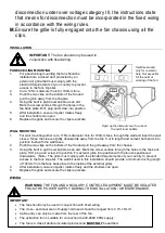
IMPORTANT:

 The fan should only be used in  


conjunction with fixed wiring. 


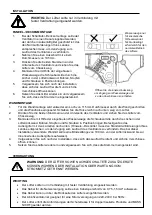
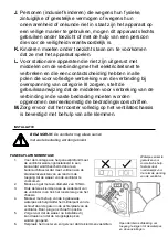
PANEL/CEILING MOUNTING 

1. 

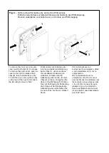
For panel/ceiling mounting the fan should be 
installed into a closed duct protected by an 
exterior air grille that must comply with the 
standard requirements of your country to prevent 
access to the fans impeller. 

2. 

Cut a 105mm diameter hole for 100mm fans. 

3. 

Push the two clips on the bottom of the fan and 
pull the grille away from the chassis. 

4.  

Using the built in spirit level bubble as an aid.  
Mark the screw centres through the holes in the 
fan back plate. Drill, plug and screw into position. 

5. 

After installation, ensure impeller rotates freely 
and the shutters can open. 

6. 

Replace the grille and ensure the clips reactivate.  


WALL MOUNTING  

1. 

For wall mounting either cut a 115mm diameter hole for 100mm fans, through the wall and insert the wall 
sleeve. Slope the sleeve slightly downwards away from the fan. Cut to length and cement both ends into 
position flush with the wall faces.  

2. 

Push the two clips on the bottom of the fan and pull the grille away from the chassis. 

3.  

Using the built in spirit level bubble as an aid.  Mark the screw centres through the holes in the fan back 
plate. Drill, plug and screw into position. Fix exterior grille into position with the louvres positioned 
downwards.  (Note:- The grille must comply with the standard requirements of your country to prevent 
access to the fans impeller. The wall kit used in this installation should provide a minimum ducting length 
of 100mm from the fans back plate to the inside of the external grille).  

4. 

After installation, ensure impeller rotates freely and the shutters can open. 

5. 

Replace the grille and ensure the clips reactivate. 

 
WIRING


WARNING: 

THE FAN AND ANCILLARY CONTROL EQUIPMENT MUST BE ISOLATED 

FROM THE POWER SUPPLY DURING THE INSTALLATION / OR MAINTENANCE. 


IMPORTANT 

  The fan should only be used in conjunction with fixed wiring.  

  The cross - sectional area of supply cord used should be ranged from 0.75-1.5mm

2

  Cable entry can only be made from the rear of the fan.  

  The extraction fan is suitable for connection to 220-240V 50Hz supply.  

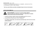
  The fan is a class ll double insulated product and 

MUST NOT 

be earthed. 

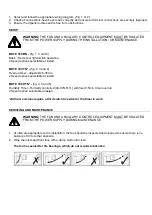
Open up the internal cover to access 

the spirit level bubble 

Spirit level used 
only for cosmetic 
help. Not essential 
for the normal 
working of the fan. 

Содержание 8000001232

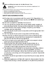
Страница 1: ...T LES ILLUSTRATIONS CONSERVEZ CES INSTRUCTIONS POUR POUVOIR Y REVENIR EN CAS DE BESOIN BITTE LESEN SIE DIE ANWEISUNGEN GEMEINSAM MIT DEN ABBILDUNGEN BITTE BEWAHREN SIE DIESE ANWEISUNGEN AUF LEES DE INSTRUCTIES EN BEKIJK DE ILLUSTRATIES BEWAAR DEZE INSTRUCTIES Installation and Wiring Instructions EN Installations und Verdrahtungsanweisungen DE Montage en bedradingsinstructies NL MUTE IPX5 220 240V ...

Страница 2: ...hould only be used in conjunction with the appropriate Vent Axia products F The Fan should only be used in conjunction with fixed wiring G When the Fan is used to remove air from a room containing a fuel burning appliance ensure that the air replacement is adequate for both the fan and the fuel burning appliance H The Fan should not be used where it is liable to be subject to direct water spray fo...

Страница 3: ...ement both ends into position flush with the wall faces 2 Push the two clips on the bottom of the fan and pull the grille away from the chassis 3 Using the built in spirit level bubble as an aid Mark the screw centres through the holes in the fan back plate Drill plug and screw into position Fix exterior grille into position with the louvres positioned downwards Note The grille must comply with th...

Страница 4: ...verrun timer adjustable 5 30min 2 Speed options selectable at install MUTE 100 HTN fig 2 3 and 5 Humidity Timer Humidity controlled 40 90 R H with fixed 15min timer overrun 2 Speed option selectable at install All timer versions require a third switch live wire for the timer to work SERVICING AND MAINTENANCE WARNING THE FAN AND ANCILLARY CONTROL EQUIPMENT MUST BE ISOLATED FROM THE POWER SUPPLY DUR...

Страница 5: ...hrt werden B Der Lüfter ist für die Installation ab Zone 2 geeignet C Der Lüfter sollte mit einem lokalen Trennschalter ausgestattet werden der in der Lage ist alle Pole mit einer Kontaktentfernung von mindestens 3 mm zu trennen D Der Lüfter sollte mit einem lokalen Trennschalter ausgestattet sein der alle Pole mit einem Kontaktabstand von mindestens 3 mm trennen kann E Stellen Sie sicher dass die...

Страница 6: ...sicht oder Anleitung hinsichtlich der Verwendung des Geräts durch eine für die Sicherheit verantwortlichen Person erfolgt L Kinder sollten überwacht werden um sicherzustellen dass das Gerät nicht als Spielzeug verwendet wird M Stationäre Geräte die nicht mit Mitteln zur Trennung vom Versorgungsnetz ausgestattet sind mit einer allpoligen Kontakttrennung die eine vollständige Trennung unter der Über...

Страница 7: ...serwaage die Schraubenmitte durch die Löcher in der Lüfterrückwand Bohren Stopfen und Schrauben in Position bringen Befestigen Sie das Außengitter mit den Lamellen nach unten Hinweis Das Gitter muss den Standardanforderungen Ihres Landes entsprechen um den Zugang zum Laufrad des Ventilators zu verhindern Das bei dieser Installation verwendete Wandkit sollte eine Mindestlänge von 100 mm von der Lüf...

Страница 8: ...tallation auswählbar MUTE 100 HTN fig 2 3 und 5 Ventilator mit Feuchtigkeitssensor 40 90 R F und Nachlauftimer Fester voreingestellter 15 min Nachlauftimer 2 Geschwindigkeitsoptionen bei der Installation auswählbar Alle Timer Versionen erfordern ein drittes Live Kabel damit der Nachlauftimer funktioniert INSTANDHALTUNG UND WARTUNG WARNUNG DER LÜFTER SOWIE NACHGESCHALTETE STEUERGERÄTE MÜSSEN WÄHREN...

Страница 9: ...r moet voorzien zijn van een aan uitschakelaar die in staat is alle polen te scheiden die een contactscheiding hebben van minimaal 3 mm D Zorg dat de netvoeding voltage frequentie fase overeenkomt met het informatielabel E De ventilator mag alleen samen met geschikte Vent Axia producten worden gebruikt F De ventilator mag alleen samen met vaste bedrading worden gebruikt G Wanneer de ventilator wor...

Страница 10: ... is bevestigd met behulp van alle klemmen INSTALLATIE BELANGRIJK De ventilator mag alleen samen met vaste bedrading worden gebruikt PANEEL PLAFONDMONTAGE 1 Voor de montage aan het paneel plafond moet de ventilator worden geïnstalleerd in een kanaal dat wordt beschermd door een buitenluchtrooster dat moet voldoen aan de standaardvereisten van uw land om de toegang tot de waaier van de ventilator te...

Страница 11: ...men vastzitten BEDRADING WAARSCHUWING DE VENTILATOR EN ONDERSTEUNENDE CONTROLEAPPARATUUR MOET GEÏSOLEERD WORDEN VAN DE STROOMVOORZIENING TIJDENS DE INSTALLATIE OF HET ONDERHOUD 1 Kies het juiste aansluitschema en volg dit op Fig 1 of 2 2 Controleer of alle verbindingen juist zijn aangesloten en dat alle contactaansluitingen en kabelklemmen goed vast zitten 3 Controleer dat de waaier vrij draait en...

Страница 12: ...EN ONDERHOUD WAARSCHUWING DE VENTILATOR EN DE BIJBEHORENDE REGELAPPARATUUR MOETEN TIJDENS HET ONDERHOUD WORDEN GEÏSOLEERD VAN DE STROOMTOEVOER 1 Controleer en reinig de ventilator met de voor de installatie geschikte tussenpozen om te voorkomen dat er zich vuil of andere afzettingen ophopen 2 Veeg de inlaten en voorkant schoon met een vochtige doek De ventilator heeft gesealde voor levensduur gesm...

Страница 13: ...Fig 1 MUTE 100 BN Fig 2 MUTE 100 TN MUTE 100 HTN 220 240V 50Hz 220 240V 50Hz N L LS 3 AMP MAX 3 AMP MAX ...

Страница 14: ...inneren und äußeren Abdeckung beide Clips 1 um sie zu lösen Um die äußere Abdeckung zu entfernen schieben Sie die Abdeckung nach rechts um die 4 Clips 2 zu lösen und gehen Sie dann in Ihre Richtung 3 Richten Sie zum Anbringen der Abdeckung die 4 Clips auf der Rückseite der Abdeckung aus und schieben Sie sie nach links bis Sie ein Klicken hören Om de binnencover en buitencover te verwijderen drukt ...

Страница 15: ...GERSINN um den eingestellten Punkt zu reduzieren Dies macht den Sensor MEHR empfindlich Vochtigheidssensor instellen 40 90 R V Draai de potmeter rechtsom om het INSTELPUNT TE VERHOGEN Dit maakt de sensor MINDER gevoelig Draai de potmeter linksom om het INSTELPUNT TE VERMINDEREN Dit maakt de sensor MEER gevoelig Timer Adjustment JP5 Speed selection JP2 The fan is factory set to low speed with jumpe...

Страница 16: ...oor recyclingadvies www vent axia nl www vent axia de 495837 B 0120 The Guarantee Applicable only to products installed and used in the Netherlands or Germany For details of guarantee outside these countries contact your local supplier Vent Axia guarantees its products for two years from date of purchase against faulty material or workmanship In the event of any part being found to be defective th...

Отзывы: