VMM501
V. 01 – 17/01/2019
8
©Velleman nv
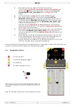
5.2
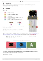
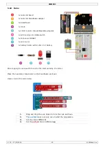
Button
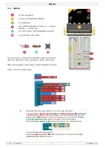
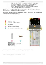
1x micro:bit board
1x micro:bit breadboard adapter
1x breadboard
2x red LED (polarisation: anode (+) = long leg,
cathode (-) = short leg)
2x 100 Ω resistor (brown/black/brown/gold)
1x momentary push button
We use a button to control the LED flash. Press the button to
make the LED flash in turns. Release to switch off the LED.
Place the necessary components on the breadboard as shown.
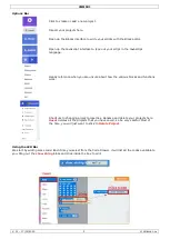
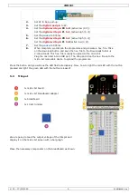
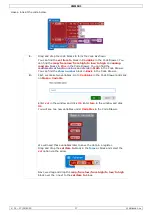
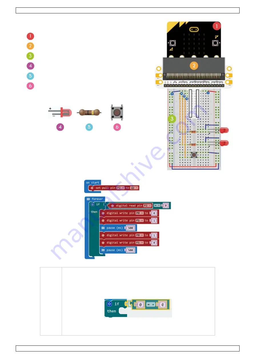
Have a look at the code below.
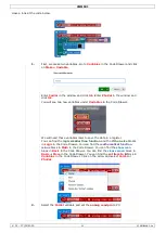
1.
Drag and drop the code blocks to form the code as shown.
You can find the
digital read pin
P0
and
digital write pin
P0
to
0
blocks
in
Advanced
Pins
in the Code Drawer. You can find the
forever
and
pause (ms)
100
in
Basic
in the Code Drawer. You can find the
if then
and
logic equal function
blocks in
Logic
in the Code Drawer.
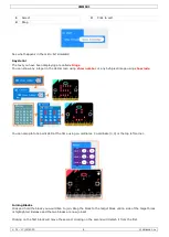
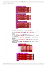
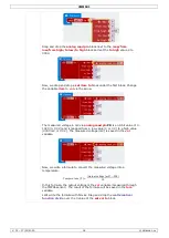
Drag the
logic equal function
block and drop it over the
true
block.
The two blocks will snap together.
Drag the
digital read pin
P0
block and drop it over the
0
of the
logic
equal function
block as shown.


