DVR4H5
V. 01 – 03/06/2014
5
©Velleman nv
Rear panel
LAN port
Connect the DVR to a local network by plugging a network cable into this port.
VGA
Connector for video monitor (not included).
AUDIO IN
4 audio input channels to connect four external audio sources, e.g. from cameras with audio.
AUDIO OUT
1 audio output to connect to an audio device, e.g. a speaker (mono).
VIDEO IN
4 video input channels to connect 4 external video sources, e.g. cameras.
HDMI
1 video output channel to connect the DVR to the main monitor.
EXTERNAL I/O
Use a 9-pin DSUB connector to connect external signals, e.g. alarm, PTZ…
12V DC
Power supply input
6.
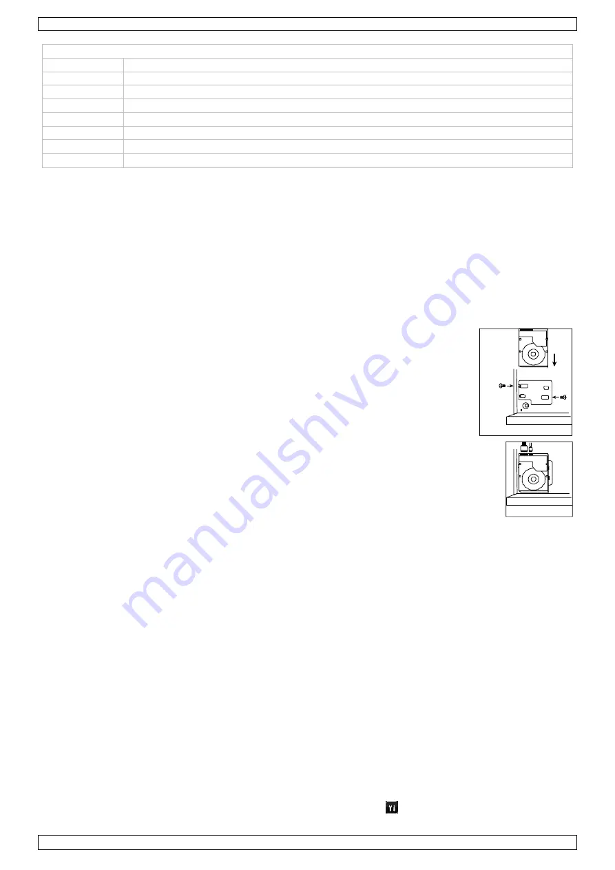
Installing a SATA hard disk
A SATA hard disk (not included) must be installed before the DVR is powered on.
Notes
•
It is not recommended to use a green hard disk in this device. Refer to the manual on the cd for a list of compatible hard
disks.
•
It is recommended to clear all data in the hard disk when the DVR is powered on and the date & time are set correctly to
ensure the recorded data are not mixed with other data previously saved in the same hard disk. Refer to the manual on
the cd for details.
Installation
1
Loosen the screws on the upper cover and remove it from the DVR.
The cover is made of metal. Be careful not to hurt yourself to its edge.
2
Place the hard disk to the bracket, and fasten it with the supplied screws.
Make sure the PCB side of the hard disk is facing up
3
Connect the power and data bus cables to the hard disk.
4
Close the upper cover of the DVR and fasten the screws you loosened in step 1.
7.
Hardware Setup
Refer to the illustrations on page 2 of this manual.
Connecting a Video Monitor
Obtain a suitable monitor (not included) and connect it to the HDMI or VGA video output port on the back of the DVR.
Connecting the Power Supply
1.
Plug the DC output connector of the included power adaptor into the VDC power input at the back of the DVR.
WARNING:
only use the included adaptor.
2.
Plug the included power cable into the adaptor input connector and plug the other end into the mains.
Do not
switch the
DVR on yet.
Connecting a Camera
1.
You can connect up to four suitable cameras. Each camera needs its own power supply.
2.
Connect the video output of the camera to either video input at the back of the DVR. The number next to the input
connectors represents the channel number. Connector type is BNC.
Connecting Audio
1.
The DVR supports four audio inputs. Connect the audio output of an audio source to an audio input of the DVR. Make
sure to connect the audio channel to the corresponding video channel. Connector type is BNC.
2.
There is also an audio output connector. Connect an audio device, e.g. a speaker to this connector when desired.
Connector type is BNC.
Connecting Local Area Network (LAN)
Connect the DVR to a local network by plugging a network cable into the LAN port at the back of the DVR. Connector type is
8P8C (RJ45). To setup the network connection, press the Menu button and select
. Refer to the full manual on the included
CD-ROM for details.
Front Panel
screw hole
Front Panel


