background image

18 

Issue  V1.0  (2014-01-10) 

Table 5-1 lists the image setting parameters. 

Table 5-1


Image setting parameters 

Parameter 

Description 

Setting 

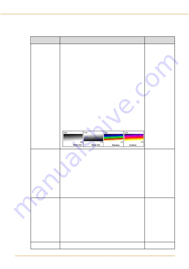
Polarity/LUT 

The temperatures of the temperature fields 
detected by the thermal imaging camera are 
separately mapped to values ranging from 0 to 
255 by the algorithm. In the black/white display 
mode, this range is converted to the grayscale 
tones. For example, 0 indicates completely 
black, and 255 indicates completely white. The 
temperature field of the scene is converted to 
images by using the grayscale ranging from 0 to 
255. Different polarity modes can be converted
to different display images. The most common
setting is white hot (a hotter object is displayed
brighter than a colder object) or black hot (a
hotter object is displayed darker than a colder
object). The difference between two modes lies
in that the temperatures corresponding to the
darker one and the lighter one are reversed.
Other modes include rainbow and ironbow.

[How to set] 

Select from the 
drop-down list 
box. 

[Default value] 

White hot 

Dynamic DVE 

The sharpness of normal thermo graphic images 
is lower than the visible light and it is difficult to 
use the normal thermo graphic images to 
identify the original images of the targets. The 
image enhancement and edge processing 
technology can be used to get better recognition 
and distinguishing effects. The dynamic DVE is 
classified into six levels, ranging from 0 to 6. 
You can set the DVE according to an actual 
requirement.   

[How to set] 

Select by 
dragging the 
slider. 

[Default value] 

Level 1 

Contrast 

The contrast indicates a contrast between light 
and dark images. The higher the value, the 
greater the contrast, the darker the dark place, 
and the brighter the bright place; the smaller the 
value, the smaller the contrast, and the smaller 
the difference between bright and dark. The 
contrast classified into four levels, ranging from 
1 to 4. You can set the contrast according to an 
actual requirement.   

[How to set] 

Select by 
dragging the 
slider. 

[Default value] 

Level 4 

Mirror 

Providing the selection of image pixel locations. 

[How to set] 

Thermal Imaging Integrated Network Camera 

User Manual 

Parameter Setting 

Содержание VPIP-THERMAL-XX22

Страница 1: ...VPIP THERMAL XX22 Thermal Imaging Integrated Network Camera User Manual Issue V1 0 10 Date 2014 01...

Страница 2: ...wing symbols whose meanings are described accordingly Symbol Description It alerts you to fatal dangers which if not avoided may cause deaths or severe injuries It alerts you to moderate dangers which...

Страница 3: ...his device is installed in places where thunder and lightning frequently occur ground the device nearby to discharge high energy such as thunder strikes in order to prevent device damage Unless otherw...

Страница 4: ...her heat equipment Keep the device away from moist dusty extremely hot or cold places or places with strong electric radiation If the device is installed outdoors take insect and moisture proof measur...

Страница 5: ...control in the Internet Explorer 12 4 3 3 In the Google Firefox or Safari browsers watch real time video 13 4 4 Setting Local Network Parameters 13 5 Parameter Setting 17 5 1 Sensor Configuration Int...

Страница 6: ...ion Area 28 6 2 3 Alarm configuration 30 2 2 4 Mapping configuration 32 2 2 5 Text Picture Message Alarm SMS MMS 33 2 2 6 Temperature curves Query 34 7 Technical Specifications 36 A Hazardous Substanc...

Страница 7: ......

Страница 8: ...uflaged and hidden target in both day and night Therefore it achieves real 24 hour surveillance Monitoring the temperature field of the target heat distribution The infrared thermal camera can display...

Страница 9: ...imaging integrated network camera For details about the multi connector combination cable see Table 1 2 Figure 1 2 Multi connector combination cable Power Network cable Data control line Table 1 1 Mul...

Страница 10: ...ture trends alarm Temperature Measurement Model Supports H 264 BP MP HP MJPEG four optional coding algorithms and strong compatibility Real time 3 streams output to meet local storage and network tran...

Страница 11: ...V1 0 2014 01 10 2 Device Dimensions Figure 2 1 shows the dimensions of the thermal imaging integrated network camera Dimensions unit mm Thermal Imaging Integrated Network Camera User Manual Device Dim...

Страница 12: ...allation tools Tools Appearance Phillips screwdriver prepare by yourself Claw hammer prepare by yourself Hammer drill prepare by yourself Spirit level prepare by yourself T15 ring spanner delivered wi...

Страница 13: ...Installation Procedure Step 1 Remove the installation location labels delivered with the camera Stick the installation location labels on the ceiling or the wall as shown in Figure 3 1 NOTE If the ins...

Страница 14: ...e on the wall as shown in Figure 3 2 Figure 3 2 Fixing base Step 4 Align If using on the Vehicle Bone please install the Shock absorber first in the bottom of PTZ before fixing the PTZ End Thermal Ima...

Страница 15: ...amera default value 192 168 0 120 in the address box and press Enter The login page is displayed as shown in Figure 4 1 Figure 4 1 Login page Step 2 Input the User and password The default name is adm...

Страница 16: ...out Table 4 1 lists the elements on the main page layout Figure 4 2 Main page layout Table 4 1 Elements on the main page N O Element Description 1 Real time video area Real time videos are displayed i...

Страница 17: ...djust the PTZ rotation speed Enable or disable 3D position Set the direction to due north Set the PTZ timer NOTE PTZ timer function as a time trigger When it is activated the PTZ rotates according to...

Страница 18: ...mer level and set Download unsigned ActiveX control and initialize and script ActiveX controls not marked as safe for scripting under ActiveX controls and plug ins to Enable as shown in Figure 4 4 Fig...

Страница 19: ...ActiveX Click the message jump to download ActiveX control interface once downloading is complete you can watch more fluent video screen Unable to display video picture and need to download and insta...

Страница 20: ...rol interface once downloading is complete you can watch more fluent video screen 4 3 3 In the Google Firefox or Safari browsers watch real time video Google Firefox and Safari browsers only support A...

Страница 21: ...e is displayed as shown in Figure 4 7 Figure 4 7 Local Network page Step 2 Set the parameters according to Table 4 2 Table 4 2 Local network parameters Parameter Description Setting IP Protocol IPv4 i...

Страница 22: ...0 120 Subnet Mask Subnet mask of the network adapter Setting method Enter a value manually Default value 255 255 255 0 Default Gateway This parameter must be set if the client accesses the device thr...

Страница 23: ...twork Camera User Manual Quick Configuration Thermal module Step 3 Click OK If the message Network Parameter Updated is displayed click OK The system saves the settings The message Set network pram s...

Страница 24: ...ace select and right click the surveillance image to the set as shown in Figure 5 1 Figure 5 1 Sensor configuration Step 2 Choose Sensor Configuration The Sensor Configuration dialog box is displayed...

Страница 25: ...o set Select from the drop down list box Default value White hot Dynamic DVE The sharpness of normal thermo graphic images is lower than the visible light and it is difficult to use the normal thermo...

Страница 26: ...al imaging camera may comprise the mechanical action correction mechanism that can periodically improve the image quality This component is called flat field correction FFC When controlling the FFC th...

Страница 27: ...s not automatically perform the FFC based on the temperature change or the specified period You can press the Do FFC button to select the manual FFC mode When you feel that the image is obviously degr...

Страница 28: ...FFC button 5 4 DNR Figure 5 4 shows the DNR interface Figure 5 4 DNR interface Table 5 3 lists the DNR parameters Table 5 3 Parameters on the DNR interface Parameter Description Setting 3DNR Decrease...

Страница 29: ...ature is for outside environment it is changeable for user and inside cavity temperature is not editable c Recommended to use inside temperature for ambient temperature when environment temperature ch...

Страница 30: ...ssue V1 0 2014 01 10 23 Figure 5 6 Temp detection configure 5 7 Temp detection area configuration Figure 5 7 Temp area selection Thermal Imaging Integrated Network Camera User Manual Parameter Setting...

Страница 31: ...Alarm configuration menu Step 2 Default is full screen area one two three four five optional Step 3 Under normal circumstances target emissivity is applied with 0 95 When need to monitor special mate...

Страница 32: ...n mode change the emissivity and target distance that is change the target emissivity and distance in all regions b Alarm threshold and trends alarm can enable at same time but the system defaults to...

Страница 33: ...the installation When installation succeed there will be a icon NVMS in the desktop click to open the login page Input the default user and password admin admin and choose the language then click log...

Страница 34: ...d display the temperature in the live window of Thermal image Thermal configure menu There are 6 sub menus under Thermal Menu 6 2 1 Temperature detection paratemeters The first sub menu Temperature de...

Страница 35: ...can choose if to display the highest temperature on the screen Allow to switch off Alarm snapshot or on Temperature detection parameters page 6 2 2 Detection Area Detection Area Allow customer to set...

Страница 36: ...2014 01 10 29 Detection area page On the live video the temperature of selected area will be displayed as below Example Thermal Imaging Integrated Network Camera User Manual NVMS Temperature Detectio...

Страница 37: ...Alarm means when temperature reach to that value there is some event like fire or high temperature existed Trends alarm Trends alarm happens in an interval time 10 minutes During this time if Thermal...

Страница 38: ...Issue V1 0 2014 01 10 31 Alarm configuration page Real time alarm interface Thermal Imaging Integrated Network Camera User Manual NVMS Temperature Detection Settings...

Страница 39: ...tion Used for the dual vision Thermal Optical mode To allow the temperature displayed on the normal optical window Configuration page Dual window Thermal PTZ Thermal Imaging Integrated Network Camera...

Страница 40: ...customer demand specifically integrate third party SMS MMS alarm module can be realized the target area exceeds the alarm threshold send the target information includes geographic location to the user...

Страница 41: ...below fore reference Wireless SMS MMS modem 2 2 6 Temperature curves Query This function allows query the highest temperature curves of the full screen or a selected area Temperature curves query The...

Страница 42: ...Issue V1 0 2014 01 10 35 When find the logs double click to see the curve Example full screen high temperature Thermal Imaging Integrated Network Camera User Manual NVMS Temperature Detection Settings...

Страница 43: ...Sense method Micro bolometer Pixel distance 25um Response waveband 8 14um NETD 50mK Fixed lens 50 mm Aperture F value 1 Focusing mode Manual adjustment FOV field of view 11 9o 9o P color mode Black h...

Страница 44: ...R 22X Optical Lens F 4 7mm F1 6 103 mm F3 2 FOV field of view 58 16 2 9 H 34 31 1 64 V White balance ATW PUSH Electric shutter Auto priority shutter priority aperture priority Special functions De Fog...

Страница 45: ...protocol Max user login Max simultaneous 10 user login Rotation speed Pan 0 1 80 s Tilt 0 1 60 s Rotation angle Pan 0 360 continuous Tilt 90 90 Variable Reset point accuracy 0 1 speed Reset point quan...

Страница 46: ...eration temperature Temp 20 50 Relative humidity RH90 MAX Non condensing Protection level IP66 Installation method Wall ceiling mounting Weight 10Kg Thermal Imaging Integrated Network Camera User Manu...

Страница 47: ...eneous substances of the component is within the limit specified in SJ T 11363 2006 Requirements for Concentration Limits for Certain Hazardous Substances in Electronic Information Products indicates...

Страница 48: ...Veilux Inc 802 Greenview Dr Suite 200 Grand Prairie TX 75050 USA Toll Free 1 800 510 6528 Direct 1 214 635 4855 Fax 1 214 988 2858 sales veilux net www veilux net www veilux net...

Отзывы: