background image

44


AC310 Universal AC Drive Service Manual


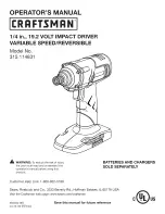
Common Mode Inductors 

L1=WCM-453228-510YT01

Maximum permissible current 

230mA


TSS Tube 

D4/D5=WES806S

  Breakdown voltage: 6.67~7.37V 

Resistances   

R39/R41=5.6K/0805

R42/R43=10K/0402

R92/R179=62Ω


R46/R47/R48=4.7K 

Capacitors 

C14/C15=1NF/0402

C19=100NF/0402

C24=2.2UF/10V 


3.6 Drive Signal Processing Circuit


1. Circuit Description:   

Содержание AC310

Страница 1: ...gment select a specific power segment There will be tips in the appendix the appendix according to the different circuits in each power section roughly divided into three power sections each power sec...

Страница 2: ...ply Boards 8 2 1 Driver Circuit 8 2 2 Brake Driver Circuit 12 2 3 Current Detection Circuit 14 2 4 Busbar Voltage Detection Circuit 16 2 5 Relay Control Circuit 18 2 6 Fan Control Circuit 20 2 7 Switc...

Страница 3: ...Maintenance 52 3 10 Current Acquisition Detection and Maintenance 53 3 11 OC Fault Detection and Maintenance 54 3 12 Wave by Wave Current Limit Comparison Circuit 56 Chapter 4 Common Faults Quick Main...

Страница 4: ...n inverted into the frequency variable and voltage variable alternating current AC through the AC drive module composed of the IGBTs and the renewal diodes and the waveforms of the voltages are Pulse...

Страница 5: ...witching Mode Power Supply The voltage at the primary side of the switching power supply transformer is taken from the DC bus voltage and through the switching power supply circuit it gets 24V 15V 5V...

Страница 6: ...in the same way as the diode In the actual measurement the forward and reverse voltage drops between each two pins should be measured a total of 6 times of which 4 times show open circuit only two tim...

Страница 7: ...f if all three legs lead out the measurement characteristics are the same as the above transistor mostly NPN tubes When using a multimeter to make the diode forward conduction at this time with anothe...

Страница 8: ...e the damage Just put a meter pen into the U V W output a meter pen on the P or N you can measure the good or bad 1 2 6 Static Measurement of Brake Units Brake Unit Schematic GBRK is the braking signa...

Страница 9: ...Driver Circuit 1 Circuit components driver circuit According to the received DSP drive signal to control the switch of IGBT optocoupler primary drive signal sampling interlocking form ACPL W314 drive...

Страница 10: ...of current to the tube after the IGBT is turned off and a too small value of this voltage spike may lead to false turn on 2 Fault type No output output out of phase module damage SC 3 Inspection Meth...

Страница 11: ...ge generated by the switching power supply is faulty Problems Measure the voltage of the drive signal on the control board when it is not in operation DC phase UH UL VH VL WH WL GND 5V 5V 5V 5V 5V 5V...

Страница 12: ...R53 1000 1206 Gate Resistor Capacitor R43 R54 R61 R68 R47 R55 1002 080 5 C41 C45 C49 C52 C43 C47 472 0805 Voltage regulator BZT52C16 Z2 Z3 Z4 Z5 Z6 Z7 Z8 Z9 Z10 Z11 Z12 Z13 Driver Optocoupler ACPL W31...

Страница 13: ...t consumed the control signal BRK voltage is 5V and when the brake is turned on the BRK voltage point is 0 455 the pulse voltage changes from 5V to 0 455V Before braking the voltage of GBRK and N poin...

Страница 14: ...6 V Refer to the selection manual for the braking resistor 4 Damage prone devices Optocouplers transistors 5 Device bit number and specification Transistors Q40 MMBT4401LT1 NPN Q41 MMBT4403LT1 PNP Gat...

Страница 15: ...and sent to the control board In addition the internal circuit of the chip detects a delay of 4us which is a large delay for the overcurrent protection function so the internal overcurrent protection...

Страница 16: ...gnetic field interference Note that pins 1 to 8 of the current detection chip ACS720 are energized during measurement because the detection chip is a differential current detection chip which can well...

Страница 17: ...perational amplifiers 2 Fault type Inaccurate bus voltage display overvoltage undervoltage 3 Inspection methods Static detection If the VPN voltage value is incorrect during the test dynamic detection...

Страница 18: ...ng Compare the value displayed by multimeter and keyboard 2 Measure the voltage at this point of the VPN get the VPN voltage from the voltage scaling relationship S2 model T3 model 579V homologous 5V...

Страница 19: ...hods provided in the appendix Dynamic test After static testing rule out device abnormalities When the DC adjustable voltage source is used to energize the bus voltage the signal source from the CPU c...

Страница 20: ...Measure the resistance value if there is resistance value and the same as the silkscreen value the resistance is normal if different and infinity it means burned out replace it Put the relay into DC24...

Страница 21: ...d the software will reboot itself twice combined with the fail safe function F10 14 it will report the fault E 040 and other switching power supply voltages will not be affected 2 Types of faults Over...

Страница 22: ...k the fan power socket voltage 0V before running 24V after running if the fan is connected at this time the power supply hiccups are judged to be a short circuited fan the voltage of FAUOUT when the f...

Страница 23: ...22 AC310 Universal AC Drive Service Manual 2 7 Switching Power Supply...

Страница 24: ...fails it will lead to bus voltage disconnection without power which will lead to the switching power supply has no power resulting in no display so in the absence of display to detect whether the 0 r...

Страница 25: ...ng 8 pin voltage of 5V the voltage is for the 3844 pin 4 to provide oscillating voltage the absence of the voltage will also lead to switching power supply problems with an oscilloscope to measure the...

Страница 26: ...0NF 0805 Diode D6 USIM 15V Circuit Resistor R21 2K 0805 Capacitance E4 220UF C12 100NF 0805 Diode D7 USIM 24V Circuit Resistor R132 R133 10 2010 R26 3K 1206 Capacitor E7 330UF C20 470PF 1206 C15 100NF...

Страница 27: ...26 AC310 Universal AC Drive Service Manual 1UF 0805 Optocoupler O1 EL250IS Controllable precision voltage regulator U2 TL431AIDBZR Diode D4 D15 US1M D5 BAV99LFIG...

Страница 28: ...g AO output TL084IDR U4 Op Amp Current sampling IU IV IW TL084IDR U4 Op Amp VPN Op amp TL084IDR U9 Comparator IU Overcurrent wave by wave current limit comparator LM239DR U8 Comparator IV Overcurrent...

Страница 29: ...Chip 74HC595D U13 CPU Keypad CPU XMC1100 T016F0032 3 2 Access to Voltage Points on the Control Board C41 C18 82 89 C95 2 2UF 0402 U17 AMS1117 3 3 Resistor R45 R51 R30 1K 0805 R20 10K 0402 R271 14 04K...

Страница 30: ...nt side 6VREF circuit Front side 10V Voltage circuit Backside 10V Voltage circuit Front side 3 3V Voltage circuit Capacitors C83 C88 100NF 0402 C87 2 2UF 0603 Resistors R25 R205 20K 0402 R164 2K 0402...

Страница 31: ...H REF L REF H2 REF L2 REF3V Black Pen GND Voltage 4 755V 1 245V 4 304 1 696V 3V 4 665 4 862 1 207 1 257 4 204 4 376 1 667 1 735 0 05V The 15V and 24V on the control board are taken directly from the...

Страница 32: ...ing will be performed REF3V is the reference power supply for the ADC module of the DSP 3V3D Circuit components 10V Circuit components Capacitors C41 C18 82 89 C95 2 2UF 0402 U17 AMS1117 3 3 Capacitor...

Страница 33: ...the control board Ordinary Optocoupler EL3H7 relay Y output EL3H4 5 way X input PUL input and ordinary input X5 multiplexed Note 1 At this time the maximum support for 5KHZ output external PG card PUL...

Страница 34: ...ce Bit Number and Specification 3 3 1 X Input Circuit Detection and Maintenance Short the 24V to the PLC use the wire to short the COM and X1 terminals check the C 14 as in Fig 1 There is a correspond...

Страница 35: ...Resistances R208 820 0402 R32 2K 0402 R33 20K 0402 R34 10K 0402 Capacitors C92 10NF Optocoupler O6 EL3HL triode vacuum tube or transistor T2 MMBT4401LT1 Diodes D1 1N4148WS 3 3 3 Relay Detection and M...

Страница 36: ...35 AC310 Universal AC Drive Service Manual 3 4 Analogue Signal Detection and Maintenance 3 4 1 Analogue Input Signal Test AI1 AI2 Voltage 0 10V Current 0 20mA...

Страница 37: ...potentiometer is 500 connect potentiometer 3 pins to 10V AI1 or AI2 and GND in turn rotate the potentiometer and check C00 16 or C00 17 if the voltage varies within 0 10V then it is normal 1 Type of...

Страница 38: ...2K 0402 R60 510 0402 R74 R75 R76 R77 2K 0402 SMD Dual Diode D6 D7 BAV99LT1G Capacitor C29 C33 100NF 0402 C106 10NF 0402 C34 1NF C30 220NF 0402 AI2 Op amp U20 B LF353DRG4 Inductor L4 0603 FBMA160808 Re...

Страница 39: ...r setting F03 37 0 F03 38 1 check C00 20 or C00 21 then press the start button there will be voltage from 0 10V after parameter setting or use multimeter DC gear measure 10V F03 38 1 check C00 20 or C...

Страница 40: ...output frequency DIP switch to A01 or AO2 frequency ON terminal at this time the parameter setting F03 37 3 F03 38 1 check C00 20 or C00 21 then press the start button there will be a frequency from...

Страница 41: ...tput Circuit Components Pulse output Resistance R21 R23 4 7K 0402 R222 10K 0402 R241 2K 0402 R204 Op amp U12 C TL084IDR Triode T4 MMBT4401LT1 Capacitance C44 100PF 0402 C43 300PF 0402 Voltage output R...

Страница 42: ...point can be in the transmit state at any time therefore the transmit circuit must be controlled by an enable signal 2 Input and output interface definitions and their metrics Input side Interface def...

Страница 43: ...0mv Logic negative level voltage 3 Implementation method and key device selection 2 Type of fault Abnormal communication communication failure reported 3 Inspection Methods Method 1 Communicate direct...

Страница 44: ...external keypad RS485 communication test method is consistent with the above 4 Repair Tips When communicating with multiple AC drives or over long distances care should be taken to detect whether 120...

Страница 45: ...YT01 Maximum permissible current 230mA TSS Tube D4 D5 WES806S Breakdown voltage 6 67 7 37V Resistances R39 R41 5 6K 0805 R42 R43 10K 0402 R92 R179 62 R46 R47 R48 4 7K Capacitors C14 C15 1NF 0402 C19 1...

Страница 46: ...whether the given voltages 3 3V and 5V on both sides of the chip are normal especially whether there is 5V on pin 20 of the chip measure the change of the CLOSE signal when there is a fault the CLOSE...

Страница 47: ...46 AC310 Universal AC Drive Service Manual 3 7 Keyboard Circuitry...

Страница 48: ...47 AC310 Universal AC Drive Service Manual 3 7 1 Keypad Key Circuit AC300CON1 V1 0 keypad adopts the analogue amplitude detection method to realize the...

Страница 49: ...esistances capacitance is normal the circuit fewer devices easy to troubleshoot 4 Device bit number and specification RUN UP Up key PGR group circuit devices Resistor R269 7 5K 0402 R163 20K 0402 R35...

Страница 50: ...y so it is very necessary to measure the pull up resistor abnormalities in the chip will lead to problems with the cathode of the segment selected LEDs or with the chip selected digital light which wi...

Страница 51: ...cuit Resistor R235 2K 0402 R219 4 7K 0402 triode Q4 Pushbutton S3 Circuit Resistor R237 2K 0402 R236 4 7K 0402 triode Q5 Pushbutton S4 Circuit Resistor R240 2K 0402 R239 4 7K 0402 triode Q6 Pushbutton...

Страница 52: ...o 5V T3 model bus voltage 1000V corresponds to 5V DSP Input Voltage Range 0 3V to 4 6V 1 If the VPN consistent unchanged the power board voltage detection circuit is abnormal test the power board VPN...

Страница 53: ...ormal voltage is 0 5V 1V If the HEAT voltage is abnormal the power board voltage detection circuit is abnormal test the power board voltage detection circuit 2 HEAT IN abnormal voltage for the control...

Страница 54: ...53 AC310 Universal AC Drive Service Manual 3 10 Current Acquisition Detection and Maintenance...

Страница 55: ...54 AC310 Universal AC Drive Service Manual 3 11 OC Fault Detection and Maintenance...

Страница 56: ...nance methods but also need to test R107 there is a foot whether the 3 3V voltage 4 IC pin voltage Note In the measurement of IC pin voltage are GND measurement it is best to use an oscilloscope to me...

Страница 57: ...56 AC310 UniversalAC Drive Service Manual 3 12 Wave by Wave Current Limit Comparison Circuit 1 Circuit description In the AC drive wave by wave current limiting CBC is very...

Страница 58: ...company is 2 times of the rated current 2 Fault type Wave by wave current limiting function will not be entered 3 Detection method Test the corresponding SMD double diode replace the comparator U7 U8...

Страница 59: ...upply repair method to repair 3 Control board problems countermeasure Replace the control board with a good board If the fault is eliminated it is the problem of the control board In the control board...

Страница 60: ...ltage Measurement method According to the method of repairing the VPN circuit on the power supply board 3 When the 24V switching power supply fails the relay cannot be absorbed so there will be voltag...

Страница 61: ...e to phase short circuit resulting in excessive current to report OC Measurement method Measure according to the measurement method of IGBT module 2 Electromagnetic interference Cause The existence of...

Страница 62: ...e temperature is too high or the ventilation of the place where the AC drive is installed is not very good 4 6 Relay Non suction Fault 1 Switching power supply 24V generates wrong voltage Cause Relay...

Страница 63: ...oltage and current of AC drive are balanced within a certain error so the current detection circuit will also report fault The current detection circuit will also report a fault Solution Check accordi...

Отзывы: