M
ode
B
P
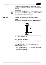
referrably as dry run protection system
.
1
2 3
F
ig
.
15
:
M
ode
B
-
D
ry run protection
M
eans with covered max
.
electrode
:
l
R
elay energises
,
connection
12
-
14
is connected through relay
l
T
ransistor output is conductive
l
C
ontrol lamp
-
O
utput lights
M
eans with uncovered max
.
electrode
(
level detection
)
or min
.
electrode
(
two
-
point control
):
l
R
elay deenergises
,
connection
12
-
13
is connected through relay
l
T
ransistor output blocks
l
C
ontrol lamp
-
O
utput extinguishes
6
.
3
S
witching point adjustment
N
ote
:
K
eep in mind for all switching point adjustments that
,
between the
momenet when the switching point is reached and the momenet when
the switching function is triggered
,
there is an integration time of
0
.
5
sec
.
T
he potentionmeter must therefore be turned slowly
.
A
possible additional integration time should only be switched on after
the adjustment
.
I
n all following applications in conjunction with an integrated resistor of
220
k
Ω
,
line monitoring of the ground and max
.
electrode is ensured
.
l
S
et the mode selection switch to mode
A
l
C
onnect the signal conditioning instrument to power supply
l
T
urn the potentiometer to position
0
l
F
ill the vessel until the max
.
electrode is covered approx
.
1
cm by
the product
l
T
urn the potentiometer slowly clockwise until the yellow signal
lamp extinguishes
L
ine monitoring
L
evel detection for max
.
signal
VEGATOR
631
E
x
•
S
ignal conditioning instrument
23
6
S
et up
23440
-
EN
-
090130


