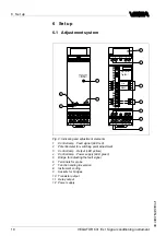
5
C
onnecting to power supply
5
.
1
P
reparing the connection
A
lways keep in mind the following safety instructions
:
l
C
onnect only in the complete absence of line voltage
l
I
f overvoltage surges are expected
,
overvoltage arresters should
be installed
T
ip
:
W
e recommend
VEGA
overvoltage arresters
B
61
-
300
(
power supply
VEGATOR
631
E
x
)
and
B
62
-
36
G
(
sensor supply
).
I
n hazardous areas you should take note of the appropriate
regulations
,
conformity and type approval certi
fi
cates of the sensors
and power supply units
.
T
he power supply can be
20
…
253
V AC
,
50
/
60
H
z or
20
…
72
V DC
.
P
ower supply of
VEGATOR
631
E
x is connected with standard cable
according to the national installation standards
.
T
he sensors are connected with standard two
-
wire cable without
screen
.
I
f electromagnetic interference is expected which is above the
test values of
EN
61326
for industrial areas
,
screened cable should be
used
.
F
rom a cable length of
50
m use one cable for each signal conditioning
instrument
.
I
f you are using a common cable
,
the min
.
and max
.
cables must be
screened
.
T
he screen must be connected the ground on both sides
.
T
ake note of the corresponding installation regulations for
E
x
applications
.
5
.
2
C
onnection procedure
M
ove on to electrical connection and proceed as follows
:
1
S
nap the socket without
VEGATOR
631
E
x onto the carrier rail
2
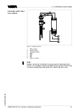
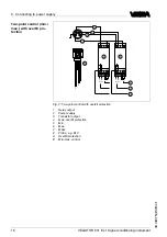
C
onnect the sensor cable to terminal
1
and
3
(
see the following
wiring plans
)
3
C
onnect power supply
(
switched o
ff
)
to terminal
9
and
10
4
I
nsert
VEGATOR
631
E
x into the plug
-
in socket and screw it down
tightly
T
he electrical connection is
fi
nished
.
N
ote safety instructions
T
ake note of
safety instruc
-
tions for
E
x ap
-
plications
S
elect power supply
S
electing connection
cable
C
able screening and
grounding
S
elect connec
-
tion cable for
E
x
applications
VEGATOR
631
E
x
•
S
ignal conditioning instrument
13
5
C
onnecting to power supply
23440
-
EN
-
090130

