background image

10

5 Set up with the display and adjustment module

VEGAPULS 66 • Foundation Fieldbus

47151-EN-210621

5  Set up with the display and adjustment 

module

5.1  Insert display and adjustment module

The display and adjustment module can be inserted into the sensor 

and removed again at any time. You can choose any one of four differ

-

ent positions - each displaced by 90°. It is not necessary to interrupt 

the power supply.
Proceed as follows:
1.  Unscrew the housing lid
2.  Place the display and adjustment module on the electronics in the 

desired position and turn it to the right until it snaps in.

3.  Screw housing lid with inspection window tightly back on
Disassembly is carried out in reverse order.
The display and adjustment module is powered by the sensor, an ad-

ditional connection is not necessary.

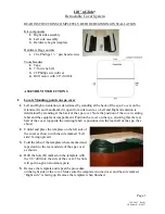
Fig. 5: Installing the display and adjustment module in the electronics compart-

ment of the single chamber housing

Содержание VEGAPULS 66 Foundation Fieldbus Standpipe...

Страница 1: ...Quick setup guide Radar sensor for continuous level measurement of liquids VEGAPULS 66 Foundation Fieldbus Standpipe version Document ID 47151...

Страница 2: ...the display and adjustment module 10 5 1 Insert display and adjustment module 10 5 2 Parameter adjustment 11 5 3 Menu overview 14 6 Set up with smartphone tablet PC notebook via Bluetooth 16 6 1 Prep...

Страница 3: ...complying with all prevailing regulations and directives The instrument must only be operated in a technically flawless and reliable condition The operator is responsi ble for the trouble free operat...

Страница 4: ...andard in field instrumentation The device fulfils the requirements of the following NAMUR recom mendations NE 21 Electromagnetic compatibility of equipment NE 53 Compatibility of field devices and di...

Страница 5: ...rity to operate this equipment 1 9 Environmental instructions Protection of the environment is one of our most important duties That is why we have introduced an environment management system with the...

Страница 6: ...class 14 ID numbers instrument documentation 15 Reminder to observe the instrument documentation The type label contains the serial number of the instrument With it you can find the following instrume...

Страница 7: ...In case of turbulences or strong product movement in the vessel long standpipe antennas should be fastened to the vessel wall 2 The measurement is only possible inside the tube the standpipe antenna m...

Страница 8: ...n nut of the cable gland and remove blind plug 4 Remove approx 10 cm 4 in of the cable mantle strip approx 1 cm 0 4 in of insulation from the ends of the individual wires 5 Insert the cable into the s...

Страница 9: ...display and adjustment module or interface adapter 3 Simulation switch 1 mode for simulation release 4 For external display and adjustment unit 5 Ground terminal for connection of the cable screening...

Страница 10: ...d by 90 It is not necessary to interrupt the power supply Proceed as follows 1 Unscrew the housing lid 2 Place the display and adjustment module on the electronics in the desired position and turn it...

Страница 11: ...ss is required 5 2 Parameter adjustment The instrument is preset by default with the suitable parameters for Application Min adjustment and Max adjustment For adaptation of the parameter Medium you ha...

Страница 12: ...ible to save the echo curve at the time of setup This is generally recommended and it is absolutely necessary if you want to use the Asset Management functions If possible the curve should be saved wi...

Страница 13: ...ause if an incorrect too large value is entered the existing level will be saved as a false signal The level would then no longer be detectable in this area If a false signal suppression has already b...

Страница 14: ...00 m d 100 00 Min adjustment 35 m 0 00 Damping Integration time 0 0 s Current output mode Output character istics 4 20 mA Failure mode 3 6 mA Current output Min Max Min current 3 8 mA Max current 20 5...

Страница 15: ...ture in C Unit SV 2 Distance in m Probe length Length of standpipe ex factory False signal suppression Linearisation Linear PIN Date Time Actual date Actual time Reset HART mode Address 0 Copy instrum...

Страница 16: ...luetooth active Off Bluetooth not active The security concept of Bluetooth operation absolutely requires that the default setting of the sensor PIN be changed This prevents unau thorized access to the...

Страница 17: ...via Bluetooth and start the search function The device auto matically searches for Bluetooth capable devices in the vicinity The message Instrument search running is displayed All devices found are li...

Страница 18: ...18 6 Set up with smartphone tablet PC notebook via Bluetooth VEGAPULS 66 Foundation Fieldbus 47151 EN 210621 Fig 9 Example of an app view Setup sensor adjustment App view...

Страница 19: ...omechanical data version IP66 IP67 and IP66 IP68 0 2 bar Options of the cable entry Cable entry M20 x 1 5 NPT Cable gland M20 x 1 5 NPT cable see below table Blind plug M20 x 1 5 NPT Closing cap NPT M...
Страница 20: ...ing scope of delivery application practical use and operat ing conditions of the sensors and processing systems correspond to the information available at the time of printing Subject to change withou...

Отзывы: