24
7 Maintenance and fault rectification
VEGACAP 67 • Two-wire
31317-EN-200929
Error
Cause
Rectification
•
The instrument signals
covered without being
covered by the meas-
ured medium
•
The instrument signals
uncovered while covered
with the measured
medium
Wrong mode selected on
the controller
Set the correct mode on the mode switch of the con-
troller (A: overflow protection, B: dry run protection).
Wiring should be carried out according to the idle cur-
rent principle.
Operating voltage too low Check operating voltage
Shortcircuit in the probe,
e.g. because of moisture in
the housing
Remove the electronics module. Check the resistance
between the marked plug connections. See the follow-
ing instructions.
Electronics defective
Push the mode switch (A/B) on the controller. If the
controller then changes the mode, the probe may be
mechanically damaged. Should the switching func-
tion in the correct mode still be faulty, return the probe
for repair.
Check if there is buildup on the probe, and if so, re-
move it.
Unfavourable installation
location
Check if the probe is covered by buildup on the socket.
Mount the instrument at a location in the vessel where
e.g. no mounds can form.
Signal lamp flashes red
Electronics module has
detected a failure
Exchange the instrument or send it in for repair
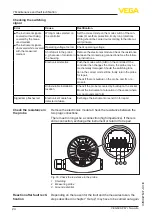
Remove the electronics module. Check the resistance between the
two plug connections.
There must no longer be a connection (high impedance). If there is
still a connection, exchange the instrument or return it for repair
1
2
3
Fig. 16: Check the resistance in the probe
1 Shielding
2 Measuring probe
3 Ground potential
Depending on the reason for the fault and the measures taken, the
steps described in chapter "
Set up
" may have to be carried out again.
Checking the switching
signal
Check the resistance in
the probe
Reaction after fault recti-
fication

