Veeder-Root EMR4 Скачать руководство пользователя страница 7

3

  EMR4 Truck Installation

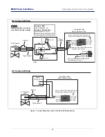
Installation of the EMR4 System involves installing the Display Head(s), the Interconnect Box, and any optional 
devices (e.g., Remote Pulser, printer, etc.). This equipment must be installed according to the applicable 
installation document. For UL/cUL installations use Control Drawing number 331940-021 and for ATEX 
installations use Descriptive System Document number 331940-022. Figure 1 shows an example dual Display 
Head installation.

Figure 1.   Example EMR4 truck Installation With 2 Display Heads And Optional Remote Pulser

DC volt

a

ge from vehicle'

s


a

cce

ss

ory

circ

u

it - 

a

t f

us

b

lock or ACC po

s

ition

of ignition 

s

witch

Di

s

play Head 1

(Meter 1)

Meter 2

Remote Di

s

play Head 2

Top mount

Remote Pul

s

er

Front mount

Remote Pul

s

er

TRUCK CAB

 OUT

S

IDE TRUCK CAB 

D

a

t

a

 (R

S

-4

8

5)

D

a

t

a

 (R

S

-4

8

5)

Power

D

a

t

a

Power 12 Vdc

Power 12 Vdc

5 Vdc

P

u

l

s

e Inp

u

t

NON-HAZARDOUS 

LOCATION

(R

S

-2

3

2)

Printer

Quick di

s

connect

fitting

s

 (option

a

l)

Temp

Probe

EPSON TM-U295 SLIP 

Cu

s

tomer 

s

upplied wiring

The following inform

a

tion i

s

 for gener

a

l reference 

a

nd i

s

 not 

intended to repl

a

ce recommended N

a

tion

a

l Electric Code (NEC) 

procedure

s

. It i

s

 import

a

nt for the in

s

t

a

ller to under

s

t

a

nd th

a

wiring loc

a

ted in Cl

ass

 I, Group D, Divi

s

ion 1 

a

nd 2 in

s

t

a

ll

a

tion

s

or Cl

ass

 I, Zone 0, Group IIA loc

a

tion

s


s

h

a

ll comply with the l

a

te

s

a

ppropri

a

te 

a

rticle

s

 found in the N

a

tion

a

l Electric Code (NFPA 

70).

Check continuity 

b

etween the Di

s

pl

a

y He

a

d ch

ass

i

s


a

nd the IB 

ch

ass

i

s

 through the vehicle fr

a

me. The re

s

i

s

t

a

nce mu

s

b

e no 

more th

a

n 1 Ohm.

24 Vdc 

Tr

u

ck gro

u

nd

M

a

x. c

ab

le length 

35 ft. (10.6 m)

M

a

x. c

ab

le length

1000 ft. (304.8 m)

HAZARDOUS LOCATION

OR

I.S.

I.S.

I.S.

I.S.

I.S.

I.S.

NOTE: Intrin

s

ic

a

lly 

sa

fe wiring 

(m

a

rked        ) 

s

h

a

ll 

b

e in

s

t

a

lled 

in 

a

ccord

a

nce with Article 504 of 

the NEC, AN

S

I/NFPA 70.

Intrin

s

ic

S

a

fety B

a

rrier

Interconnection

Box

12 AWG U.

S

. (4mm2 E.U.)

B

a

rrier Gro

u

nd

(

S

ee Notice 2)

Inp

u

t R

a

ting: 10-2

8

 Vdc, 5 A 

1.

See

Notice 2.

See

Notice 2.

2.

NOTICE

Interlock

S

witch

I.S.

E

SS

S

witch

I.S.

Содержание EMR4

Страница 1: ...Manual No 577014 322 Revision B Technical Installation Guide EMR4...

Страница 2: ...shipment as stated in our Terms and Conditions VEEDER ROOT S PREFERRED CARRIER 1 Contact Veeder Root Customer Service at 800 873 3313 with the specific part numbers and quantities that were missing o...

Страница 3: ...etallic or PVC Conduit 23 Wire Length 23 Mounting and Wiring the IB Unit 23 Solenoid Valves 23 Power Conditioning Requirements 26 Wire Size And or Distance Limitations 26 Pulse Output Limits 29 EMR4 L...

Страница 4: ...Box Wiring Connections 24 Figure 16 Example Terminal Wiring Connections For DC And AC Solenoid Valves 25 Figure 17 Digi Key Power Supply Wiring Diagram 26 Figure 18 Wiring Pulse Output To A TLS 350 Co...

Страница 5: ...CAUTION Indicates a hazardous situation which if not avoided could result in minor or moderate injury INJURY Careless or improper handling of materials can result in bodily injury GLOVES Wear gloves...

Страница 6: ...e Use All installations must be made in accordance with the accompanying Descriptive System Documentation WARNING This system operates near highly combustible fuel storage tanks FAILURE TO COMPLY WITH...

Страница 7: ...TION RS 232 Printer Quick disconnect fittings optional Temp Probe EPSON TM U295 SLIP Customer supplied wiring The following information is for general reference and is not intended to replace recommen...

Страница 8: ...nd cables are in good condition c Alternator current output is sufficient to supply EMR4 System current requirement of 5 amperes 3 Attach the wire from truck ground to the GND terminal of the Power Si...

Страница 9: ...with multiple voltage sources it may be necessary to use a separate battery or voltage source to power the EMR4 Also a battery isolator can be used between the voltage source and the IB to prevent vol...

Страница 10: ...Removed 2X 1 5 38mm 1 39 35 3mm 5 0 127mm 7 8 198mm 8 5 215 9mm w cover in place 4 04 103mm USB Port under cover 2 13 54 1mm 0 5 12 7mm 9 8 249mm 1 0 25 4mm SMA Connector under cover 4X 1 5 38mm 3X 1...

Страница 11: ...GRN GND GRN DH1 POUT A RED DH2 POUT A WHT GND BLK HALF DUPLEX RS 485 GND BLK IBNET A GRN IBNET B WHT GND GRN DH1 POUT B RED DH2 POUT B WHT GND BLK GND WHT 24V RED PRN TX BLK PRN RX GRN GND GRN DH1 POU...

Страница 12: ...en the START button is pushed on the EMR4 display both relays for that head are energized opening the solenoid valves and fast full flow is obtained First Stage Knockoff When the first stage slow flow...

Страница 13: ...to the 3 way valve junction box Pass the cable through a cord grip fitting in one of the J box openings Cut off 1 inch 25 4 mm of the cable s shield and jacket then strip off 1 2 inch 12 7 mm of each...

Страница 14: ...r hose from the 3 way valve s port 1 normally closed port to the strainer cover Connect a third hose from the 3 way valve s port 2 common port to the differential valve CAUTION Rigid Metal Junction Bo...

Страница 15: ...end pak along long length 4 As shown in C firmly squeeze the RED SIDE of the resin forcing it through the center seal and into BLACK SIDE 5 Mix thoroughly to a uniform color by squeezing contents back...

Страница 16: ...ppression Diodes can only be used with DC powered solenoids Suppressor diode V R Kit P N 846000 022 Suppressor Diode Ratings Output Current of 1 0 Amp Maximum reverse voltage 420 Volts Interconnect Bo...

Страница 17: ...iode Ratings Output Current of 1 0 Amp Maximum reverse voltage 420 Volts Suppression Diodes can only be used with DC powered solenoids Interconnect Box Power Side Terminals J7 J8 DH1 R1 NO DH1 R1 COM...

Страница 18: ...cord grip nut onto the cord grip and tighten securely Attach the shield of the temperature probe cable and or ESS switch cable to a grounding lug on the pulse encoder mounting base 5 Attach each wire...

Страница 19: ...ulse encoder Optional keypad Encoder shaft spring C C Jumper Display head terminal block Attach optional remote pulser temperature probe interlock switch IB cable and ESS switch cable shields to groun...

Страница 20: ...lay assembly and Figure 11 shows how to wire the display to the Interconnect Box You can mount the display on a wall or dashboard of a truck a wall in a building or outside in a hazardous location Use...

Страница 21: ...lled through for sealing the front cover C C switch 30 Torx screws 4 758 27 eps 30 Torx screws 4 fasten into back of Remote Display housing Adjust mounting strips to desired indents each side then tig...

Страница 22: ...s Cord grip Nut To external device 9 64 3 5 mm max To terminal block Bushing Remote Display rear cover removed Cable entries to Remote Display Attaching wires to terminal block GRN IB A INTERCONNECT...

Страница 23: ...ot manual number 577014 355 for detailed pulser mounting instructions The top mount kits P N 845900 504 845900 552 contain the remote pulser mounting plate and mounting hardware The front mount kits P...

Страница 24: ...est appropriate articles found in the National Electric Code NFPA 70 This is a control drawing only and does not reflect the actual locations of conduit entry In Installation and use of this product c...

Страница 25: ...e sult in signal loss and faulty operation 4 If you have the optional temperature probe and or ESS switch remove the lower cord grip nut and slide it then the tapered bushing over the temperature prob...

Страница 26: ...the earth At the distribution panel this is accomplished by means of a dedicated conductor buried in the earth It is imperative that all local regional and national regulations are followed when conne...

Страница 27: ...h hazards if the Display Head to IB wire runs exceed 1000 feet 304 8 m Wire runs must be less than 1000 feet to be within the limits of the UL Certification MOUNTING AND WIRING THE IB UNIT 1 The physi...

Страница 28: ...BLK RX GRN GND GRN DH1 POUT A RED DH2 POUT A WHT GND BLK HALF DUPLEX RS 485 GND BLK IBNET A GRN IBNET B WHT GND GRN DH1 POUT B RED DH2 POUT B WHT GND BLK GND WHT 24V RED PRN TX BLK PRN RX GRN GND GRN...

Страница 29: ...pressor Diode Ratings Output Current of 1 0 Amp Maximum reverse voltage 420 Volts Suppression Diodes can only be used with DC powered solenoids Interconnect Box Power Side Terminals J7 J8 DH1 R1 NO DH...

Страница 30: ...5 ampere power supply See Figure 17 for connection wiring dia gram To order visit their website at www digikey com TDK Lambda 24 volt power supply Model No HWS150A 24 A To order visit their website at...

Страница 31: ...POUT A Ground 500 feet 12V 1 072 ms 0V Pulse out waveform from EMR4 IB P1 LOW VOLTAGE DISPENSER INTERFACE MODULE PULSER P2 P3 P4 SOURCE INPUT RATING 30 VDC MAX Source voltage not required for applicat...

Страница 32: ...5VDC 24VDC 12VDC 0VDC 5VDC 24VDC 12VDC 0VDC 1 3 2 0 Ground 12V 0V To external pulse counter Setup both the EMR4 and the TLS for the same ratio of pulses to volume Reference the appropriate setup and o...

Страница 33: ...per gallon Deliver 3 200 gallons at a fueling rate of 800 gpm The actual delivery takes 4 minutes while the EMR4 takes 320 000 pulses 45 000 pulses per minute 7 minutes to process the delivery data I...

Страница 34: ...is located where neither the unit itself nor its associated cabling will be damaged by doors furniture barrows etc depot installs or nearby equipment vehicle installs Consider the ease of routing wiri...

Страница 35: ...en Ensure that all relevant subcontractors and other personnel are aware of the selected location Table 4 Remote Pulser Dimensions Operating Temperature Range Shaft Length Shaft Diameter Housing Diame...

Страница 36: ...d in an indoor non hazardous area The IB has barriers that protect the linked apparatus by an Exia intrinsically safe mode of protection and are suitable to control apparatus installed into areas that...

Страница 37: ...rements of EN 60079 11 Clause 5 7 These devices include Thermoprobe Emergency Stop Switch Corner Switch and the Optional Keypad Figures showing these devices may contain devices that are outside the s...

Страница 38: ...ors are open Ensure that all relevant subcontractors and other personnel are aware of the selected location Table A 1 System Component Information System Operating Temperature Range Height Width Depth...

Страница 39: ...For technical support sales or other assistance please visit www veeder com...

Отзывы: