28
EMR
3
- Truck Installations
EMR4 Terminal & Fueling Depot Installation
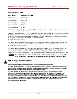
Power Conditioning Requirements
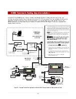
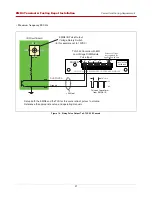
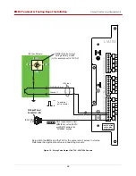
Figure 19. Wiring Pulse Output To A TLS-450/TLS4 Console
IB Circ
u
it Bo
a
rd
IB Input Power
Connector (J8)
EMR4 IB P
u
l
s
e O
u
tp
u
t
Volt
a
ge Rot
a
ry
S
witch
(In thi
s
ex
a
mple
s
et to 12VDC)
5VDC
24VDC
12VDC
0VDC
5VDC
24VDC
12VDC
0VDC
1
3
2
0
Gro
u
nd (-)
12V
0V
To extern
a
l
p
u
l
s
e co
u
nter
S
et
u
p
b
oth the EMR4
a
nd the TL
S
for the
sa
me r
a
tio of p
u
l
s
e
s
to vol
u
me.
Reference the
a
ppropri
a
te
s
et
u
p
a
nd oper
a
ting m
a
n
ua
l
s
.
LVDIM
LO
W V
O
L
T
A
GE
DI
S
PEN
S
ER INTERF
A
CE MODULE
+
-
+
-
+
-
+
-
12
11
10
9
+
-
+
-
+
-
+
-
5
6
7
8
+
-
+
-
+
-
+
-
1
2
3
4
+
-
S
OURCE
INPUT RATING
30 VDC MAX
0 1 AMP MAX
<500 feet
INPUT-PWR
GND
When supplying power from
EMR4 IB box, set switch SW1
on LVDIM PC board to the
“EXTERNAL” position.
DH1-POUT-A (+)
NOTICE


